EasyManua.ls Logo

Sony HCD-DX60AV User Manual

Sony HCD-DX60AV
76 pages
To Next Page IconTo Next Page
Page #1 background imageLoading...
Page #1 background image
SERVICE MANUAL
MINI HI-FI COMPONENT SYSTEM
US Model
AEP Model
HCD-RG70AV
E Model
HCD-DX60AV
SPECIFICATIONS
HCD-DX60AV/RG70AV
Ver 1.2 2003.07
9-873-839-13 Sony Corporation
2003G05-1 Home Audio Company
C 2003.07 Published by Sony Engineering Corporation
HCD-DX60AV/RG70AV is the tuner,
deck, CD and amplifier section in MHC-
DX60AV/RG70AV.
Dolby noise reduction manufactured under license
from Dolby Laboratories Licensing Corporation.
“DOLBY” and the double-D symbol ; are trade-
marks of Dolby Laboratories Licensing Corporation.
Model Name Using Similar Mechanism HCD-DX90
CD
CD Mechanism Type CDM58B-K6BD38
Section
Base Unit Name BU-K6BD38
Optical Pick-up Block Name KSM-213DCP
Optical Pick-up Name KSS-213D
Tape deck
Model Name Using Similar Mechanism NEW
Section
Tape Transport Mechanism Type CWL44RR-31
– Continued on next page –
Photo: HCD-RG70AV
AUDIO POWER SPECIFICATIONS:
(HCD-RG70AV US model only)
POWER OUTPUT AND TOTAL
HARMONIC DISTORTION:
with 6 ohm loads both channels driven, from
120 – 10,000 Hz; rates 60 watts per channel
minimum RMS power, with no more than 10%
total harmonic distortion from 250 milliwatts to
rated output.
Amplifier section
North American model:
HCD-RG70AV
Front speaker:
Continuous RMS power output (reference)
60 + 60 watts
(6 ohms at 1 kHz,
10% THD)
Total harmonic distortion less than 0.07%
(6 ohms at 1 kHz,
30 watts)
Center speaker:
Continuous RMS power output (reference)
40 watts
(6 ohms at 1 kHz,
10% THD)
Rear speaker:
Continuous RMS power output (reference)
40 + 40 watts
(6 ohms at 1 kHz,
10% THD)
European model:
HCD-RG70AV
Front speaker:
DIN power output (rated) 40 + 40 watts
(6 ohms at 1 kHz, DIN)
Continuous RMS power output (reference)
50 + 50 watts (6 ohms at
1 kHz, 10% THD)
Music power output (reference)
95 + 95 watts (6 ohms at 1
kHz, 10% THD)
Center speaker:
DIN power output (rated) 25 watts
(6 ohms at 1 kHz, DIN)
Continuous RMS power output (reference)
35 watts (6 ohms at 1 kHz,
10% THD)
Music power output (reference)
65 watts (6 ohms at 1 kHz,
10% THD)
Rear speaker:
DIN power output (rated) 25 + 25 watts
(6 ohms at 1 kHz, DIN)
Continuous RMS power output (reference)
35 + 35 watts (6 ohms at
1 kHz, 10% THD)
Music power output (reference)
65 + 65 watts (6 ohms at 1
kHz, 10% THD)

Table of Contents

Question and Answer IconNeed help?

Do you have a question about the Sony HCD-DX60AV and is the answer not in the manual?

Sony HCD-DX60AV Specifications

General IconGeneral
BrandSony
ModelHCD-DX60AV
CategoryStereo System
LanguageEnglish

Summary

General Information and Specifications

Audio Power Specifications

Details power output and total harmonic distortion for amplifier sections.

General Specifications

Lists technical specifications for various models and components.

General Information

Parts Identification

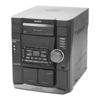
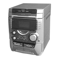
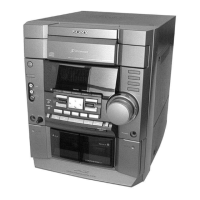
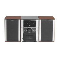
Identifies and locates various parts of the main unit for service.

Disassembly Procedures

Disassembly Flow

Provides a step-by-step procedure for disassembling the unit.

Case and Panel Removal

Details the procedure for removing the top case, CD door, and front panel.

Mechanism and Board Removal

Explains the removal of the CD mechanism, tape deck, and main board.

Base Unit and Component Boards

Covers the removal of the base unit and specific component boards.

Driver, Motor, and Sensor Boards

Details the disassembly of driver, motor, and address sensor boards.

Test Modes and Operations

System Reset and Mode Selection

Covers MC Cold Reset, CD Ship Mode, MC Hot Reset, and CD Service Mode.

Tuner and System Test Modes

Details AM tuner step change, GC Test Mode, MC Test Mode, and version display.

Electrical Adjustments

Deck Section Adjustments

Procedures for adjusting the tape deck circuits like azimuth and speed.

Tuner Section Adjustments

Adjustments for FM tuned level and null settings in the tuner section.

CD Section Checks

Verifies CD playback performance through S-curve, RF level, and balance checks.

Diagrams and Pin Functions

Block Diagrams

Illustrates signal flow for tuner, CD, main, display, and power sections.

Printed Wiring Boards (PWBs)

Shows component layouts for various boards like BD, MAIN, and PANEL.

Schematic Diagrams

Detailed circuit diagrams for BD, MAIN, REAR/CENTER AMP, and POWER AMP boards.

IC Pin Function Descriptions

Details the pin functions for key ICs, including the System Controller.

Exploded Views

Cabinet and Front Panel Exploded Views

Shows exploded views of the cabinet, front panel, and related parts.

Internal Component Exploded Views

Exploded views of the main board, CD mechanism, and base unit.

Electrical Parts List

Address Sensor Board Parts

Lists electrical components for the address sensor board.

Component Lists for Various Boards

Comprehensive lists of resistors, capacitors, diodes, and transistors.

Revision History

Related product manuals