HCD-DX10/RG4SR/RG20/RG30T
US Model
HCD-RG4SR/RG20/RG30T
Canadian Model
HCD-RG20/RG30T
AEP Model
UK Model
HCD-RG20
E Model
Australian Model
HCD-DX10
SERVICE MANUAL
Sony Corporation
Home Audio Company
Published by Sony Engineering Corporation
9-873-225-03
2003K16-1
© 2003.11
SPECIFICATIONS
Ver 1.2 2003. 11
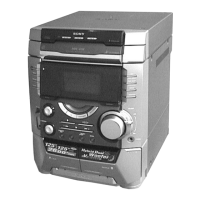
Photo : HCD-DX10
• HCD-DX10/RG4SR/RG20/RG30T is the
tuner, deck, CD and amplifier section in
MHC-DX10/RG4SR/RG20/RG30T.
Model Name Using Similar Mechanism NEW
CD
CD Mechanism Type CDM58F-K6
Section
Optical Pick-up Name
KSM-213D
Tape deck Model Name Using Similar Mechanism NEW
Section Tape Transport Mechanism Type CWL44FF29
Amplifier section
Canadian models:
HCD-RG30T
Continuous RMS power output (reference)
75 + 75 watts (6 ohms at 1
kHz, 10% THD)
Total harmonic distortion less than 0.07%
(6 ohms at 1 kHz, 50 W)
HCD-RG20
Continuous RMS power output (reference)
60 + 60 watts (6 ohms at 1
kHz, 10% THD)
Total harmonic distortion less than 0.07%
(6 ohms at 1 kHz, 30 W)
European model:
HCD-RG20
DIN power output (rated) 40 + 40 watts
(6 ohms at 1 kHz, DIN)
Continuous RMS power output (reference)
50 + 50 watts (6 ohms at 1
kHz, 10% THD)
Music power output (reference)
95 + 95 watts (6 ohms
at 1 kHz, 10% THD)
Other model:
HCD-DX10
The following measured at AC 120, 220, 240 V
50/60 Hz
DIN power output (rated) 40 + 40 watts
(6 ohms at 1 kHz, DIN)
Continuous RMS power output (reference)
50 + 50 watts (6 ohms at 1
kHz, 10% THD)
Inputs
GAME (AUDIO) IN (phono jack):
voltage 450 mV,
impedance 47 kilohms
Outputs
PHONES (stereo mini jack):
accepts headphones of
8 ohms or more
Front speaker: accepts impedance of 6 to
16 ohms
Surround speaker (HCD-RG4SR only):
accepts impedance of 6 to
16 ohms
CD player section
System Compact disc and digital
audio system
Laser Semiconductor laser
(λ=780 nm)
Emission duration:
continuous
Frequency response 2 Hz – 20 kHz (±0.5 dB)
Wavelength 780 – 790 nm
Signal-to-noise ratio More than 90 dB
Dynamic range More than 90 dB
Tape deck section
Recording system 4-track 2-channel stereo
Frequency response 40 – 13,000 Hz (±3 dB),
using Sony TYPE I
cassette
AUDIO POWER SPECIFICATIONS:
(HCD-RG4SR USA model only)
POWER OUTPUT AND TOTAL
HARMONIC DISTORTION:
with 6 ohm loads both channels driven, from
120 – 10,000 Hz; rates 100 watts per channel
minimum RMS power, with no more than 10%
total harmonic distortion from 250 milliwatts to
rated output.
Total harmonic distortion less than 0.07%
(6 ohms at 1 kHz, 50 W)
(HCD-RG30T USA model only)
POWER OUTPUT AND TOTAL
HARMONIC DISTORTION:
with 6 ohm loads both channels driven, from
120 – 10,000 Hz; rates 75 watts per channel
minimum RMS power, with no more than 10%
total harmonic distortion from 250 milliwatts to
rated output.
Total harmonic distortion less than 0.07%
(6 ohms at 1 kHz, 30 W)
(HCD-RG20 USA model only)
POWER OUTPUT AND TOTAL
HARMONIC DISTORTION:
with 6 ohm loads both channels driven, from
120 – 10,000 Hz; rates 60 watts per channel
minimum RMS power, with no more than 10%
total harmonic distortion from 250 milliwatts to
rated output.
Total harmonic distortion less than 0.07%
(6 ohms at 1 kHz, 30 W)
MINI HIFI COMPONENT SYSTEM
— Continued on next page —