1515
HCD-DX10/RG4SR/RG20/RG30T
SECTION 5
DIAGRAMS
Note on Schematic Diagram:
• All capacitors are in µF unless otherwise noted. pF: µµF
50 WV or less are not indicated except for electrolytics
and tantalums.
• All resistors are in Ω and
1
/
4
W or less unless otherwise
specified.
•
f
: internal component.
• C : panel designation.
Note on Printed Wiring Boards:
• X : parts extracted from the component side.
• b : Pattern from the side which enables seeing.
• Indication of transistor.
Note:
The components identi-
fied by mark 0 or dotted
line with mark 0 are criti-
cal for safety.
Replace only with part
number specified.
Note:
Les composants identifiés par
une marque 0 sont critiques
pour la sécurité.
Ne les remplacer que par une
piéce portant le numéro
spécifié.
• A : B+ Line.
• B : B– Line.
• H : adjustment for repair.
• Voltages and waveforms are dc with respect to ground
under no-signal (detuned) conditions.
• Voltages are taken with a VOM (Input impedance 10 MΩ).
Voltage variations may be noted due to normal produc-
tion tolerances.
no mark : FM
< >: CD
[ ] : TAPE
• Waveforms are taken with a oscilloscope.
Voltage variations may be noted due to normal produc-
tion tolerances.
• Circled numbers refer to waveforms.
• Signal path.
F : FM
E : PB (DECK A)
d : PB (DECK B)
G : REC (DECK B)
J : CD
THIS NOTE IS COMMON FOR PRINTED WIRING BOARDS AND SCHEMATIC DIAGRAMS.
(In addition to this, the necessary note is printed in each block.)
C
B
These are omitted.
E
Q
B
These are omitted.
CE
Q
• Abbreviation
CND : Canadian model
AUS : Australian model
AR : Argentina model
SP : Singapore model
TW : Taiwan model
MX : Mexican model
MY : Malaysia model
E2 : 120V AC Area in E model
E3 : 240V AC Area in E model
E51 : Chilean and Peruvian model
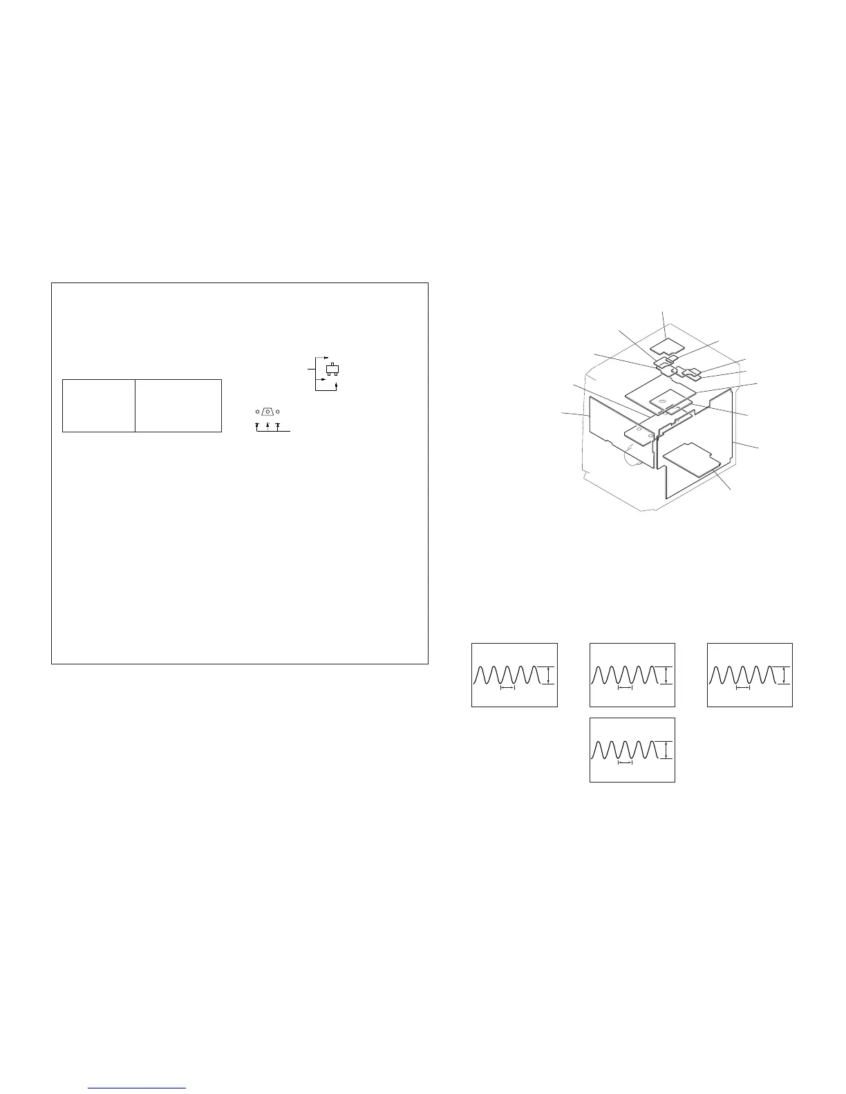
5-1. CIRCUIT BOARD LOCATION
• WAVEFORMS
– MAIN BOARD – – PANEL BOARD –– CD BOARD –
MOTOR board
ADDRESS SENSOR board
SENSOR board
DRIVER board
TRANS board
VIDEO OUT board
SPDL board
SUB TRANS board
MAIN board
POWER board
PANEL board
CD board
1
IC751 rf (XOUT)
4.9Vp-p
59 ns
2 IC102 wf (XOUT)
3.2Vp-p
222
µ
s
4 IC601 qj (XTAL 6.0MHz)
4.8Vp-p
167 ns
3 L251
14.1Vp-p
16.6
µ
s
(60.1 kHz)


 To Next Page