EasyManua.ls Logo

Sony HCD-DX50 User Manual

Sony HCD-DX50
76 pages
To Next Page IconTo Next Page
Page #1 background imageLoading...
Page #1 background image
MHC-DX50/RG80
Canadian Model
MHC-RG80
Australian Model
E Model
MHC-DX50
SERVICE MANUAL
MINI Hi-Fi COMPONENT SYSTEM
Sony Corporation
Audio Entertainment Group
General Engineering Dept.
Ver 1.0 2001. 02
9-929-588-11
2001B1600-1
© 2001.2
COMPONENT MODEL NAME
MHC-DX50/RG80 are composed of following models.
As for the service manual, it is issued for each component model,
then, please refer to them.
REAR SPEAKER
SYSTEM
COMPACT DISC DECK
RECEIVER SYSTEM
FRONT SPEAKER
SYSTEM
PARTS LIST
Part No. Description Remark
ACCESSORIES & PACKING MATERIALS
********************************
1-476-503-11 REMOTE COMNDUDER (RM-SR210)
1-501-374-11 ANTENNA, LOOP
1-501-659-71 ANTENNA, (FM)
4-210-254-41 CUSHION (FOOT)
4-223-953-01 COVER, BATTERY (FOR RM-SR210)
4-232-650-11 INSTRUCTION MANUAL (
DX50 : AUS, E2, E51, MX,SP/RG80)
(ENGLISH)
4-232-650-21 INSTRUCTION MANUAL
(DX50 : E2, SP/RG80)(FRENCH)
4-232-650-31 INSTRUCTION MANUAL
(DX50 : E2, E51, MX, SP)(SPANISH)
4-232-650-41 INSTRUCTION MANUAL
(DX50 : SP)(CHINESE)
4-232-650-71 INSTRUCTION MANUAL
(DX50 : KR)(KOREAN)
MHC-RG80
HCD-RG80
SS-DX50
SS-RS50
MHC-DX50
HCD-DX50
SS-DX50
Abbreviation
E2 : 120 V AC Area in E model
E51 : Chilean and peruvian model
SP : Singapore model
MX : Mexican model
AUS : Australian model
KR : Korea model
SPECIFICATIONS
Question and Answer IconNeed help?

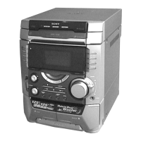
Do you have a question about the Sony HCD-DX50 and is the answer not in the manual?

Sony HCD-DX50 Specifications

General IconGeneral
BrandSony
ModelHCD-DX50
CategoryStereo System
LanguageEnglish

Summary

Specifications

Amplifier Section Specifications

Specifications for the amplifier section, including power output and input/output details.

Safety and Handling Precautions

Optical Pick-up and Laser Diode Handling

Precautions for handling the optical pick-up block and laser diode emission.

Component and Circuit Board Repair Safety

Guidelines for replacing chip components and repairing flexible circuit boards.

Safety Check-out Procedures

AC Leakage Measurement

Procedure for checking AC leakage current from exposed metal parts to ground.

Basic Operation and Setup

Section 2 Disassembly Procedures

Upper Case (Top) Removal

Procedure for removing the upper case from the main unit.

Loading Panel Assembly Removal

Steps for disassembling and removing the loading panel assembly.

Front Panel Section Disassembly

Procedure for disassembling the front panel section of the unit.

Panel Board Removal

Instructions for removing the panel board.

Section 3 Test Mode Operations

Resets and Tuner Step Configuration

Procedures for cold/hot resets and changing tuner AM channel steps.

Function and GC Test Mode

Selecting external inputs and using GC test mode for system checks.

MC Test Mode Functions

Checking amplifier, tuner, and tape section operations in MC test mode.

Section 4 Mechanical Adjustments

Section 5 Electrical Adjustments

Deck Section Adjustment Precautions

General precautions and settings for deck section electrical adjustments.

Head Azimuth and Tape Speed Adjustments

Adjusting head azimuth and tape speed for deck sections.

Playback Level Adjustment

Adjusting playback level for Deck A and Deck B using a level meter.

Record Bias and Level Adjustment

Adjusting record bias and record level for Deck B.

Tuner Section Adjustments

CD Section Adjustments

Section 7 Exploded Views

Section 8 Electrical Parts List

Exploded View and Parts List

Related product manuals