19
HCD-DX2D
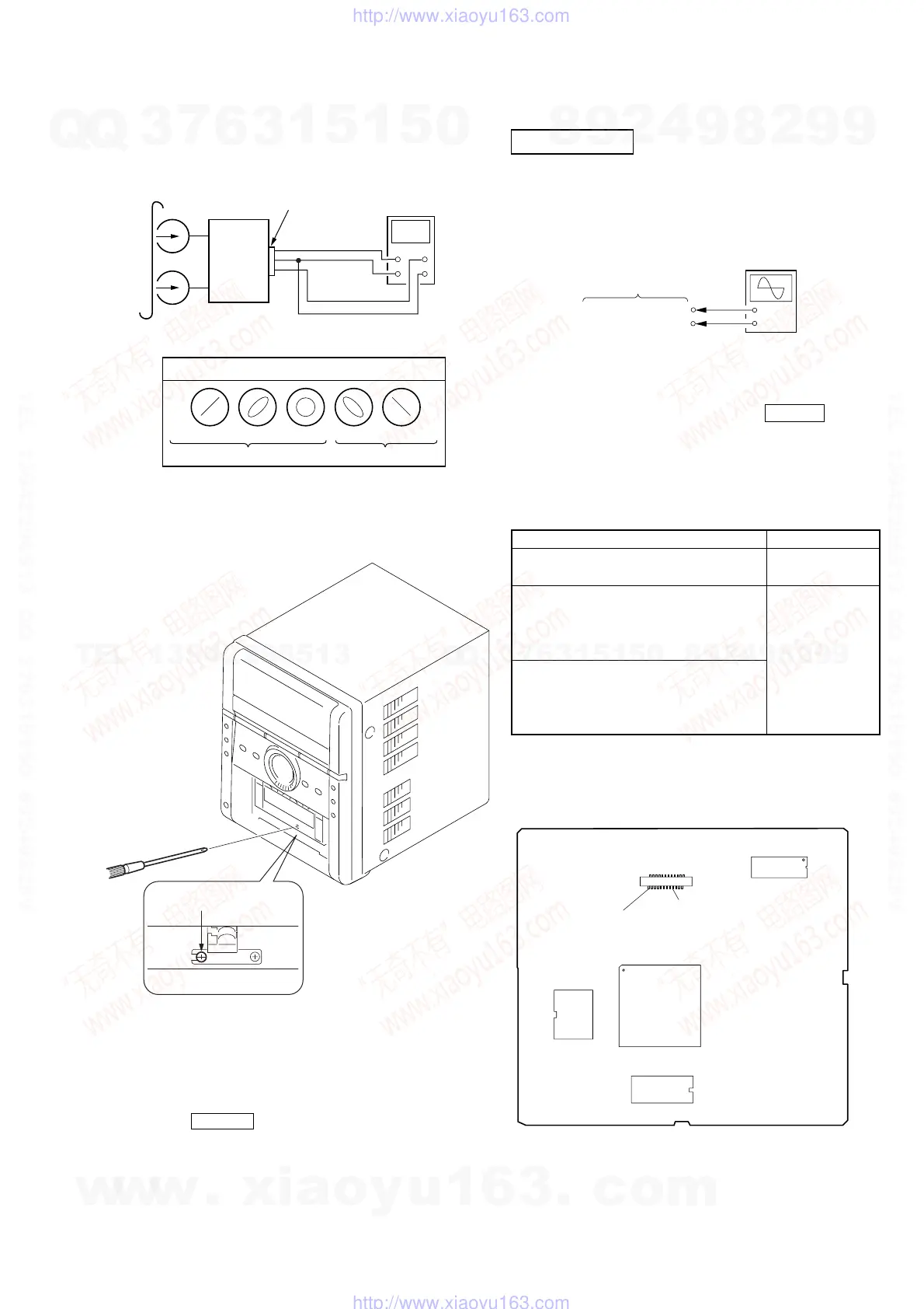
4. After the adjustments, apply suitable locking compound to
the parts adjusted.
Adjustment Location: Record/Playback/Erase Head
3. Mode: Playback
test tape
P-4-A100
(10kHz, –10dB)
oscilloscope
set
Waveform of oscilloscope
in phase 45
°
90
°
135
°
180
°
good
wrong
MAIN board
JK102
speaker terminal
L
R
DVD SECTION
[RF Level Check]
Check the RF level when optical pick-up block is replaced.
Connection:
Procedure:
1. Connect an oscilloscope to CN7 pin 8 (V-RF) and CN7 pin
wf (GND) on the MPEG board.
2. Turn the power on.
3. Set the test disc on the tray and press DVDu button to
playback.
4. Observe the waveform of the oscilloscope, and check that the
RF level is satisfied to specified value.
[Test Disc List and Specified Value]
Use the following test disc on adjustment.
Note: Do not use existing test disc for DVD.
Checking Location: MPEG board (Side A)
+
–
MPEG board
oscilloscope
CN7 pin
8
(V-RF)
CN7 pin
wf
(GND)
[Tape Speed Check]
Procedure:
1. Turn the power on.
2. Insert the WS-48B into deck.
3. Press the TAPE N button of deck.
4. Check the reading of frequency counter becomes 3000 ± 90
Hz.
Sample Value of Wow and flutter
W.RMS (JIS) less than 0.3%
(test tape: WS-48B)
TEST DISC Specified Value
CD YEDS-18 (Part No.: 3-702-101-01)
0.57 to 1.1 Vp-p
PATD-012 (Part No.: 4-225-203-01)
DVD SL (Single Layer)
NTSC :HLX-503 (Part No.: J-6090-069-A)
HLX-504 (Part No.: J-6090-088-A)
PAL :HLX-506 (Part No.: J-6090-077-A)
0.58 to 1.23 Vp-p
DVD DL (Dual Layer)
NTSC :HLX-501 (Part No.: J-6090-071-A)
HLX-505 (Part No.: J-6090-089-A)
PAL :HLX-507 (Part No.: J-6090-078-A)
Note: Refer to “3-12. PANEL CASS (CASSETTE)” (see page 16)
adjustment screw
U2
IC7
IC4
IC6
24
23
1
2
CN7 Pin
wf
(GND)
CN7 Pin
8
(V-RF)
CN7
— MPEG Board (SIDE A) —
Ver. 1.2
w
w
w
.
x
i
a
o
y
u
1
6
3
.
c
o
m
Q
Q
3
7
6
3
1
5
1
5
0
9
9
2
8
9
4
2
9
8
T
E
L
1
3
9
4
2
2
9
6
5
1
3
9
9
2
8
9
4
2
9
8
0
5
1
5
1
3
6
7
3
Q
Q
TEL 13942296513 QQ 376315150 892498299
TEL 13942296513 QQ 376315150 892498299
http://www.xiaoyu163.com
http://www.xiaoyu163.com