Do you have a question about the Sony HCD-DV2D and is the answer not in the manual?
Guidelines for replacing chip components, avoiding heat damage.
Precautions for handling and soldering flexible circuit boards.
Information on characteristics and usage of unleaded solder.
Details model variations and their respective power voltage needs.
Maps system buttons to their respective page numbers for quick access.
Explains the operation and purpose of each button on the remote.
Provides a step-by-step sequence for disassembling the unit.
Instructions for accessing internal components by removing the top cover.
Steps to access the main board during disassembly.
Step-by-step guide on how to access diagnostic modes.
Instructions for performing system controller diagnostics.
Guide to accessing and using MPEG-related test functions.
Details torque values for tape deck mechanisms.
Step-by-step guide for aligning the record/playback head.
Procedure to verify tape speed accuracy.
Setting the deck section to a specific voltage level.
Procedure for measuring RF signal levels on the MPEG board.
Illustrates the signal path within the MPEG-1 section.
Detailed circuit diagram for the main board.
Component layout for the MPEG board.
Visual breakdown of all major components.
Detailed illustration of front panel parts.
Exploded diagram of the chassis and associated parts.
Lists capacitors, transistors, and resistors for the AMP section.
Lists capacitors and resistors for the MPEG section.
Lists components for the power board.
| Brand | Sony |
|---|---|
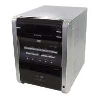
| Model | HCD-DV2D |
| Category | Stereo System |
| Language | English |