Do you have a question about the Sony HCD-D690 and is the answer not in the manual?
Details about the CD player mechanism, pick-up, and related components.
Details about the CD player mechanism, pick-up, and related components.
Details about the tape transport mechanism, including its type.
Power output and total harmonic distortion for audio specifications.
Specifies voltage and frequency requirements for different models.
Lists power consumption in watts for various models.
Physical dimensions of the unit in mm and inches.
Weight of the unit in kg and lbs.
List of items included with the product.
Procedure for testing AC leakage from exposed metal parts to earth ground.
General warnings about potential hazards during operation or adjustment.
Guidelines for replacing chip components, especially tantalum capacitors.
Precautions and tips for repairing flexible circuit boards.
Precautions for handling the optical pick-up block due to electrostatic discharge.
Guidelines for safely checking laser diode emission from the optical pick-up block.
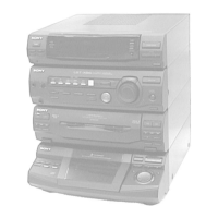
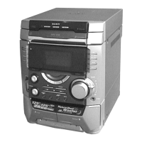
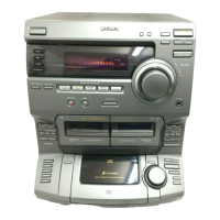
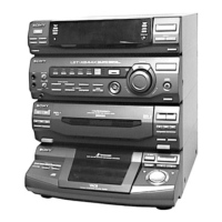
Shows model identification based on the back panel labels.
Step-by-step guide on how to set up and begin using the receiver.
Instructions for setting the clock time on the unit.
Guide on how to store favorite radio stations for quick access.
Instructions on how to connect outdoor antennas for optimal reception.
Guidance on connecting external audio components to the system.
Steps for connecting a turntable to the audio system.
General instructions on how to use the primary functions of the device.
Detailed steps on how to play a compact disc using the unit.
Guide on how to tune into and listen to radio broadcasts.
Instructions on how to record content from a CD to a tape.
Steps for recording audio from an external source onto a tape.
Instructions on how to play cassette tapes using the unit.
Continuation of instructions for playing cassette tapes.
Guide for performing high-speed dubbing from one tape to another.
Details on how to use the various DJ effects available on the unit.
General information and operation of the CD player section.
How to play CDs without stopping between tracks.
Steps for programming a sequence of tracks to play from a CD.
Instructions for recording CDs with custom track order selection.
Information on manually operating the tape deck.
Continuation of DJ effects, potentially related to track specification.
How to loop a specific section of audio from a CD.
Guide on how to adjust the sound settings, including equalizer and bass/treble.
Details on how to use the graphic equalizer to shape the sound.
How to choose different audio emphasis modes for sound profiles.
Steps for fine-tuning the audio emphasis settings.
How to create and save custom sound profiles for personal use.
Instructions for using the karaoke function to sing along with music.
How to adjust the microphone echo effect for singing or voice input.
Steps to turn off or cancel the microphone echo.
How to mix audio sources and record sounds from various inputs.
Setting the unit to wake up to music at a specific time.
How to set the unit to record radio programs automatically.
Steps to cancel a previously set timer recording.
Instructions for disassembling the main case of the unit.
Steps for disassembling the front panel assembly.
Procedure for removing and accessing the main circuit board.
Disassembly steps for the main section of the unit.
Procedure for disassembling the CD mechanism deck section.
Steps for disassembling the tape mechanism deck section.
Procedure for removing the cassette lid assembly.
Steps for disassembling the CD lid assembly.
Procedure for removing the panel A and B sub assemblies.
Disassembly of the base unit, including yoke bracket and boss.
Steps for removing and adjusting the disc table assembly.
Disassembly of the BD board, including screws, springs, and flat wire.
Steps for removing the optical pick-up and sled motor components.
Disassembly of the audio board, including connectors and rivets.
Procedure for removing the capstan motor and belts.
Resets the unit to factory default conditions, clearing all preset data.
Moves the CD pickup to a position suitable for vibration resistance during transport.
Resets the unit while retaining stored preset data, similar to power cycling.
Allows free movement of the CD sled motor, useful for cleaning the pickup.
Option to switch external input terminal names between VIDEO and MD.
Allows adjustment of AM channel tuning step between 9kHz and 10kHz.
Activates all LEDs and the display, enabling key check and function testing.
Mode for checking CD and tape deck operations, performing automated sequences.
Important precautions to follow before performing mechanism adjustments.
Specifications and procedures for measuring torque on various mechanisms.
Specifications and procedures for measuring tape tension.
Adjustments for the tape deck section, including head demagnetization and azimuth.
List of test tapes and their usage for various adjustments like azimuth and speed.
Procedure for adjusting the azimuth of the record/playback heads for optimal audio quality.
Procedure for adjusting the tape speed to ensure accurate playback.
Steps for adjusting the playback audio level for optimal output.
Adjusting the bias current for recording to optimize tape performance.
Procedure for setting the recording level for optimal audio input.
Adjusting the tuned level for AM reception to ensure clear signal detection.
Adjustments related to the FM tuner section, including tuned level and stereo detection.
Procedure for adjusting the tuned level for FM reception.
Specific FM adjustment procedure for EE and CIS models, focusing on polar adjustments.
General notes regarding CD block operations and adjustments.
Procedure to check and adjust the focus bias for the optical pick-up.
Method for checking the S-curve waveform to ensure symmetrical signal output.
Procedure to check the RF signal level output from the CD player.
Method to check the E-F balance and track jump performance of the CD player.
Diagram showing the physical location of various circuit boards within the unit.
Oscilloscope waveforms for different ICs and sections, used for diagnostics.
Block diagram illustrating the tuner section for specific regional models.
Block diagram illustrating the tuner section for AEP and UK models.
Block diagram illustrating the tuner section for EE and CIS models.
Block diagram detailing the CD player's optical pick-up, motor drives, and signal processing.
Block diagram illustrating the main control and processing circuitry of the unit.
Block diagram for the BD section, showing IC connections and signals.
Printed wiring board layout for the BD section, showing component placement.
Schematic diagram for the CD motor control board, showing its circuitry.
Printed wiring board layout for the CD motor section.
Schematic diagram for the tuner section covering US, CND, E, AR, MX models.
Printed wiring board layout for the tuner section of US, CND, E, AR, MX models.
Schematic diagram for the tuner section of AEP and UK models.
Printed wiring board layout for the tuner section of AEP and UK models.
Schematic diagram for the tuner section of East European and CIS models.
Printed wiring board layout for the tuner section of East European and CIS models.
Printed wiring board layouts for the tape deck section's various boards.
Schematic diagram for the tape deck section, detailing its circuitry.
Schematic diagram for the main control and processing section of the unit.
Printed wiring board layout for the main section, showing component placement.
Printed wiring board layouts for the various panel sections of the unit.
Schematic diagrams for the panel sections, illustrating their electronic circuits.
Printed wiring board layouts for the power supply section.
Schematic diagram for the power supply section, detailing its circuitry.
Block diagrams for ICs within the BD section, illustrating their pin functions and internal logic.
Block diagrams for ICs within the BD section, illustrating their pin functions and internal logic.
Block diagram for the IC controlling the CD motor.
Block diagrams for ICs within the tuner section, showing their functions.
Block diagrams for ICs within the tuner section, illustrating their functions.
Block diagrams for ICs used in the tape deck section.
Block diagrams for ICs found in the main control section.
Block diagrams for ICs found in the main control section.
Detailed pin function description for IC301 on the main board.
Continued pin function descriptions for various ICs on the main board.
Continued pin function descriptions for various ICs on the main board.
Pin function description for IC601 on the panel board.
Exploded view of the rear panel and case assembly, with part numbers.
Exploded view of the front panel section 1, showing components and fasteners.
Exploded view of the front panel section 2, illustrating various buttons and indicators.
Exploded view of the chassis, showing main boards, power transformer, and connectors.
Exploded view of the tape mechanism deck section 1, showing levers, springs, and dampers.
Exploded view of the tape mechanism deck section 2, illustrating head assemblies, sliders, and gears.
Exploded view of the tape mechanism deck section 3, showing cams, levers, belts, and motors.
Exploded view of the CD mechanism deck section, detailing its components and assembly.
Exploded view of the base unit section, including optical pick-up, BD board, and motors.
List of electrical parts for the audio section, including capacitors, connectors, ICs, transistors, and resistors.
List of electrical parts for BD, CD motor, CD-A SW, TC-A SW, and TC-B SW boards.
List of electrical parts for BD, CD motor, CD-A SW, TC-A SW, and TC-B SW boards.
List of electrical parts for power amp, table sensor, TC-A SW, and TC-B SW boards.
List of electrical parts for headphone-mic, leaf switch, LED, and main boards.
List of electrical parts for the main section, including capacitors, connectors, diodes, and transistors.
List of electrical parts for the main section, including transistors and resistors.
List of electrical parts for the main section, including resistors.
List of electrical parts for the main panel, including resistors, capacitors, connectors, diodes, and vibrators.
List of electrical parts for the panel and power amp sections.
List of electrical parts for the panel and power amp sections.
List of electrical parts for TCB and TRANS boards, including resistors, transistors, and connectors.
List of electrical parts for TCB and TRANS boards, including capacitors, diodes, and resistors.
List of electrical parts for the TCB board, including capacitors, transistors, and diodes.
List of electrical parts for the TCB board, including transistors, resistors, and filters.
List of electrical parts for the TCB board, including transistors, resistors, and switches.
List of electrical parts for the TCB board, including resistors.
List of electrical parts for TCB and TRANS boards, including variable resistors, terminals, vibrators, connectors, fuses, and transformers.
List of hardware components such as screws, rings, and pins used in the assembly.
List of included accessories like remote commander, antenna, and manuals.
Revision note regarding the TEST MODE section, directing to specific pages.
Revision note regarding the ELECTRICAL ADJUSTMENTS section, directing to specific pages.
Revision note regarding the BLOCK DIAGRAMS (MAIN SECTION), directing to specific pages.
Resets the unit to factory default conditions, clearing all preset data.
Moves the CD pickup to a position suitable for vibration resistance during transport.
Resets the unit while retaining stored preset data, similar to power cycling.
Allows free movement of the CD sled motor, useful for cleaning the pickup.
Allows adjustment of AM channel tuning step between 9kHz and 10kHz.
Mode for checking CD and tape deck operations, performing automated sequences.
| Brand | Sony |
|---|---|
| Model | HCD-D690 |
| Category | Stereo System |
| Language | English |