Do you have a question about the Sony HCD-D790 and is the answer not in the manual?
Power output and total harmonic distortion for amplifier and speaker sections.
Warning about controls, adjustments, and procedures leading to hazardous radiation exposure.
Statement about the laser component's radiation level and Class 1 classification.
Post-service safety checks, including antenna terminals, metal parts, and AC leakage.
Warning about components critical to safe operation and replacement procedures.
Precautions for handling optical pick-up blocks due to electrostatic discharge.
Safety instructions for checking laser diode emission to avoid exposure.
Procedure for tuning and memorizing radio stations for FM and AM bands.
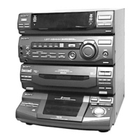
Overview of the disassembly sequence for the set.
Step-by-step instructions and diagram for removing the upper case.
Step-by-step instructions and diagram for disassembling the front panel.
Step-by-step instructions and diagram for accessing the main board.
Step-by-step instructions and diagram for disassembling the main section.
Step-by-step instructions and diagram for disassembling the CD mechanism.
Step-by-step instructions and diagram for disassembling the tape mechanism.
Diagrams and identification for optical pick-up and sled motor.
Overview of various test modes for CD section and tape deck.
Procedure to reset memory and preset data to initial conditions.
Procedure to reset the set similar to power cord unplugging.
Method for activating and operating the aging mode for the CD section.
Method for activating and operating the aging mode for the tape deck section.
General precautions and procedures for mechanical adjustments.
Measurement procedures and values for torque on various modes.
Measurement procedures and values for tape tension.
General precautions for deck section electrical adjustments.
Procedure for adjusting head azimuth for Deck A and Deck B.
Procedure for adjusting tape speed for Deck A, including test tape and frequency counter.
Procedure for adjusting playback level for both decks using a test tape and level meter.
Procedure for adjusting record bias current for Deck B, including test signals and oscilloscope.
Procedure for adjusting record level for Deck B, using test signals and frequency counter.
Procedure for adjusting the AM tuned level using SSG and a loop antenna.
Procedure for adjusting the FM tuned level using SSG and coaxial cable.
Detailed procedure for FM polar adjustment, including connection diagrams and test points.
Procedure for checking and adjusting focus bias, with waveform examples.
Procedure for checking the RF signal level with waveform examples.
Procedure for checking E-F balance and track jump, including waveform analysis.
Block diagram illustrating the signal flow and components in the CD section.
Schematic diagram for the tuner section (East European, CIS models).
Schematic diagram for the main section, showing interconnections.
Schematic diagram for the BD section, including component interconnections.
Schematic diagram for the tuner section (AEP, UK models), with waveform and IC references.
Schematic diagram for the deck section, covering audio, motor, and switch boards.
Schematic diagram for the power section, including power amp and transformer boards.
Schematic diagram for the main section (part 1 of 5), showing power and control signals.
Schematic diagram for the main section (part 2 of 5), showing IC interconnections.
Schematic diagram for the main section (part 4 of 5), showing power supply and output stages.
Schematic diagram for the main section (part 5 of 5), showing input stages and ICs.
Detailed pin functions for IC301 (Main Control) on the Main Board.
Exploded view and parts list for the tape mechanism deck (section 1).
Exploded view and parts list for the tape mechanism deck (section 2).
Exploded view and parts list for the tape mechanism deck (section 3), including motor board.
Warning about critical components and replacement guidelines.
| CD Player | Yes |
|---|---|
| Tuner | AM/FM |
| USB Port | No |
| Remote Control | Yes |
| Power Output | 100W |
| Audio Formats Supported | CD-DA |
| Dimensions | 290 x 268 x 168 mm |
| Weight | 5.5 kg |
| Functions | CD, Radio, Cassette |
| Speakers | 2 |