— 18 —
SECTION 4
MECHANICAL ADJUSTMENTS
SECTION 5
ELECTRICAL ADJUSTMENTS
DECK SECTION
PRECAUTION
1. Clean the following parts with a denatured-alcohol-moistened
swab:
record/playback head pinch roller
erase head rubber belts
capstan idlers
2. Demagnetize the record/playback head with a head
demagnetizer.
3. Do not use a magnetized screwdriver for the adjustments.
4. After the adjustments, apply suitable locking compound to the
parts adjusted.
5. The adjustments should be performed with the rated power
supply voltage unless otherwise noted.
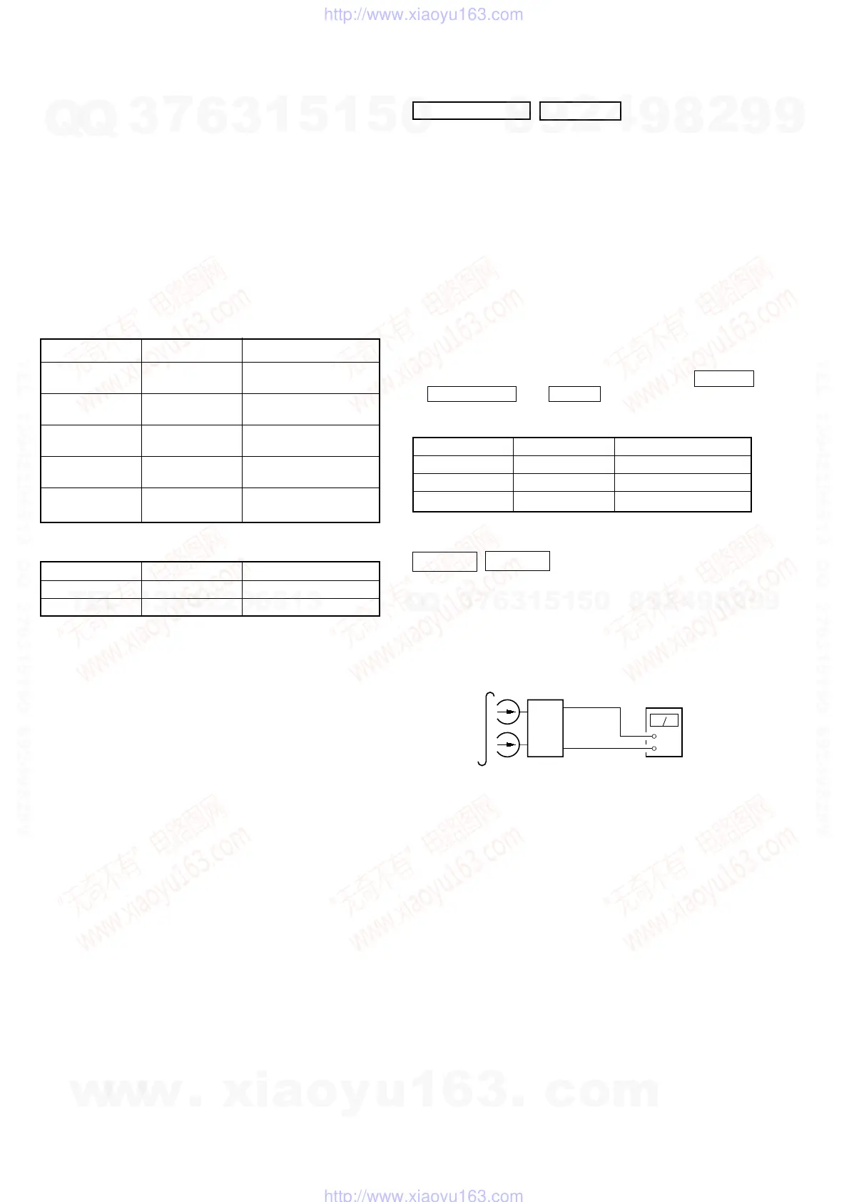
• Torque Measurement
• Tape Tension Measurement
Mode Torque Meter Meter Reading
Forward CQ-102C
36 to 61g·cm
(0.50 – 0.84 oz·inch)
Forward
CQ-102C
2 to 6g·cm
Back Tension (0.026 – 0.082 oz·inch)
Reverse CQ-102RC
36 to 61g·cm
(0.50 – 0.84 oz·inch)
Reverse
CQ-102RC
2 to 6g·cm
Back Tension (0.026 – 0.082 oz·inch)
FF, REW CQ-201B
61 to 143g·cm
(0.85 – 1.98 oz·inch)
Mode Tension Meter Meter Reading
Forward CQ-403A more than 100g (3.52 oz)
Reverse CQ-403R more than 100g (3.52 oz)
0dB=0.775V
1. Demagnetize the record/playback head with a head
demagnetizer. (Do not bring the head demagnetizer close to
the erase head.)
2. Do not use a magnetized screwdriver for the adjustments.
3. After the adjustments, apply suitable locking compound to the
parts adjust.
4. The adjustments should be performed with the rated power
supply voltage unless otherwise noted.
5. The adjustments should be performed in the order given in this
service manual. (As a general rule, playback circuit adjustment
should be completed before performing recording circuit
adjustment.)
6. The adjustments should be performed for both L-CH and R-
CH.
7. Switches and controls should be set as follows unless otherwise
specified.
8. Set to test mode. (Press key switch same time GROOVE
ENTER/NEXT and DISC 4 button.)
• Test Tape
Tape Signal Used for
P-4-A100 10kHz, –10 dB Azimuth Adjustment
WS-48B 3kHz, 0dB Tape Speed Adjustment
P-4-L300 315Hz, 0dB Level Adjustment
Record/Playback Head Azimuth Adjustment
DECK A DECK B
Note: Perform this adjustments for both decks
Procedure:
1. Mode: Playback (FWD)
set
main board
CN207
Pin
1
(L-CH)
Pin
3
(R-CH)
main board
CN207
Pin
2
+
–
level meter
test tape
P-4-A100
(10KHz, –10dB)
w
w
w
.
x
i
a
o
y
u
1
6
3
.
c
o
m
Q
Q
3
7
6
3
1
5
1
5
0
9
9
2
8
9
4
2
9
8
T
E
L
1
3
9
4
2
2
9
6
5
1
3
9
9
2
8
9
4
2
9
8
0
5
1
5
1
3
6
7
3
Q
Q
TEL 13942296513 QQ 376315150 892498299
TEL 13942296513 QQ 376315150 892498299
http://www.xiaoyu163.com
http://www.xiaoyu163.com