EasyManua.ls Logo

Sony HCD-DR8AV User Manual

Sony HCD-DR8AV
92 pages
To Next Page IconTo Next Page
Page #1 background imageLoading...
Page #1 background image
HCD-DR8AV/W900AV
US Model
Canadian Model
HCD-W900AV
E Model
Australian Model
HCD-DR8AV
SERVICE MANUAL
COMPACT DISC DECK RECEIVER
Model Name Using Similar Mechanism
HCD-DR4/DR5/DR6/DR440/
W300/W5000/XB500
CD Mechanism Type CDM37M-5BD32L
Base Unit Name BU-5BD32L
Optical Pick-up Name KSS-213D/Q-N
Model Name Using Similar Mechanism NEW
Tape Transport Mechanism Type TCM-230AWR2/230PWR2
HCD-DR8AV/W900AV is the tuner, deck, CD and
amplifier section in LBT-DR8AV/W900AV.
— Continued on next page —
SPECIFICATIONS
CD
Section
Tape deck
Section
Ver 1.1 2003. 05
Sony Corporation
Home Audio Company
Published by Sony Engineering Corporation
9-928-902-12
2003E16-1
© 2003.05
Amplifier section
LBT-W900AV
Front Speaker:
Continuous RMS power output (Reference)
100 + 100W
(8 at 1 kHz, 10% THD)
Total harmonics distortion Less than 0.07%
(8 at 1 kHz, 50W)
Center Speaker:
Continuous RMS power output (Reference)
45W
(8 at 1 kHz, 10% THD)
Rear Speaker:
Continuous RMS power output (Reference)
40 + 40W
(8 at 1 kHz, 10% THD)
LBT-DR8AV
Front Speaker:
The following measured at AC 120/220/240V, 50Hz
DIN power output (Rated) 130 + 130W
(6 at 1 kHz, DIN)
Continuous RMS power output (Reference)
160 +160W
(6 at 1 kHz, 10% THD)
Center Speaker:
DIN power output (Rated) 30W
(8 at 1 kHz, DIN)
Continuous RMS power output (Reference)
40W
(8 at 1 kHz, 10% THD)
Rear Speaker:
DIN power output (Rated) 30 + 30W
(8 at 1 kHz, DIN)
Continuous RMS power output (Reference)
40 + 40W
(8 at 1 kHz, 10%
THD)
Inputs
PHONO IN (phono jacks): sensitivity 3mV,
impedance 47k
MIX MIC (phone jack): sensitivity 1mV,
impedance 10k
VIDEO1 IN (phono jacks): sensitivity 250mV,
impedance 47k
VIDEO2 IN (phono jacks): sensitivity 250mV,
impedance 47k
MD IN (phono jacks): sensitivity 450mV,
impedance 47k
(LBT-DR8AV/W900AV)
DVD IN (phono jacks): sensitivity 450mV,
impedance 47k
Outputs
PHONES (stereo phone jack):
accepts headphones of 8
or more
VIDEO OUT (phono jack): voltage 250mV,
impedance 1k
MD OUT (phono jacks): voltage 250mV, impedance
1k
WOOFER OUT (phono jack):
voltage 1V, impedance
1k
FRONT SPEAKER:
(LBT-W900AV) accepts impedance of 8 to
16
(LBT-DR8AV) accepts impedance of 6 to
16
CENTER SPEAKER: accepts impedance of 8 to
16
REAR SPEAKER: accepts impedance of 8 to
16
Video section
Inputs
VIDEO1 IN (phono jacks): 1Vp-p, 75
VIDEO2 IN (phono jacks): 1Vp-p, 75
Output
VIDEO OUT (phono jack): 1Vp-p, 75
Photo: HCD-DR8AV

Table of Contents

Question and Answer IconNeed help?

Do you have a question about the Sony HCD-DR8AV and is the answer not in the manual?

Sony HCD-DR8AV Specifications

General IconGeneral
BrandSony
ModelHCD-DR8AV
CategoryStereo System
LanguageEnglish

Summary

Service Manual - HCD-DR8AV/W900AV

Model Identification

Identifies US, Canadian, E, and Australian models for service.

Specifications Overview

System Specifications

Safety Check-Out Procedures

AC Leakage Measurement Guidelines

Details AC leakage limits and measurement methods for safety.

Servicing Notes for CD Section

Handling Optical Pick-up and Laser Diode

Provides precautions for handling optical pick-up and laser diode.

General Information and Disassembly

Service Modes and Adjustments

Front Panel Controls and Layout

Location of Front Panel Parts and Controls

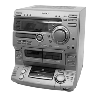
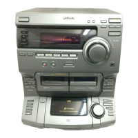
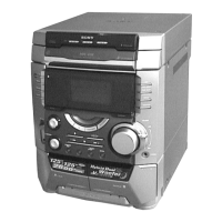
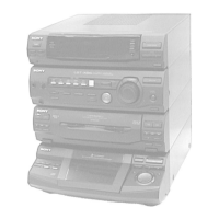
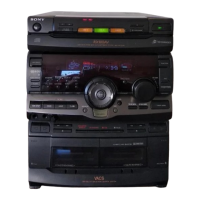
Identifies all buttons, knobs, and connectors on the front panel.

Disassembly - Front Panel

Disassembly - Main Board

Main Board Removal Steps

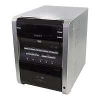
Illustrates and describes the removal of the main board.

Service Modes - Basic Operations

Service Modes - Advanced Tests

CD Player Error Handling

Error History Display Mode

Describes the mode for checking CD player mechanical and disc errors.

Mechanical Adjustments

Torque Measurement and Head Azimuth

Covers torque measurement procedures and head azimuth adjustment.

Tape Speed and Playback Level Adjustments

Adjusting Tape Speed and Playback Level

Procedures for adjusting tape speed and playback levels for decks.

Tape Deck Record Adjustments

Record Bias and Level Adjustment (Deck B)

Procedures for adjusting record bias and level on deck B.

CD Section Checks

S Curve, RF Level, and E-F Balance Checks

Explains checks for S curve, RF level, and E-F balance.

Diagrams Overview

Circuit Board Locations and BD Block Diagram

Shows board layout and BD section block diagram.

Deck Section Block Diagram

Main Section Block Diagram (1/2)

Main Section Block Diagram (2/2)

Power Section Block Diagram (DR8AV)

Power Section Block Diagram (W900AV)

Display Section Block Diagram

Waveform Analysis

BD, Main, and FL Section Waveforms

Displays key waveforms for BD, Main, and FL sections.

Printed Wiring Boards - BD Section

Schematic Diagram - BD Section

BD Board Schematic

Provides the schematic diagram for the BD board.

Printed Wiring Board - Main Section (1/5)

Schematic Diagram - Main Section (1/5)

Main Board (1/5) Schematic

Presents the schematic diagram for the main board, part 1 of 5.

Schematic Diagram - Main Section (2/5)

Main Board (2/5) Schematic

Presents the schematic diagram for the main board, part 2 of 5.

Schematic Diagram - Main Section (3/5)

Main Board (3/5) Schematic

Presents the schematic diagram for the main board, part 3 of 5.

Schematic Diagram - Main Section (4/5)

Main Board (4/5) Schematic

Presents the schematic diagram for the main board, part 4 of 5.

Schematic Diagram - Main Section (5/5)

Main Board (5/5) Schematic

Presents the schematic diagram for the main board, part 5 of 5.

Schematic Diagram - Deck Section

Audio Board Schematic

Provides the schematic diagram for the audio board within the deck section.

Printed Wiring Board - Deck Section

Schematic Diagram - Power Section (DR8AV - 1/2)

Schematic Diagram - Power Section (DR8AV - 2/2)

Printed Wiring Board - Power Section (DR8AV)

Printed Wiring Board - Power Section (W900AV)

Schematic Diagram - Power Section (W900AV - 1/2)

PA Board (1/2) Schematic

Presents the schematic for the PA board, part 1 of 2, for W900AV models.

Schematic Diagram - Power Section (W900AV - 2/2)

PA Board (2/2) Schematic

Presents the schematic for the PA board, part 2 of 2, for W900AV models.

Schematic Diagram - FL Section

FL Board Schematic

Provides the schematic diagram for the FL (Fluorescent) display board.

Printed Wiring Board - FL Section

Schematic Diagram - Panel VR Section

Panel VR Board Schematic

Provides the schematic diagram for the panel VR board.

Printed Wiring Board - Panel VR Section

Schematic Diagrams - TC Panel Section

TC-A, TC-B, and LED Panel Board Schematics

Presents schematic diagrams for TC-A, TC-B, and LED panel boards.

Printed Wiring Boards - TC Panel Section

Schematic Diagrams - CD Panel Section

CD-L, CD-R, Door-SW, and Front Input Schematics

Provides schematic diagrams for CD-L, CD-R, Door-SW, and Front Input boards.

Printed Wiring Boards - CD Panel Section

Schematic Diagrams - CD Motor Section

Printed Wiring Boards - CD Motor Section

Schematic Diagram - Jack Section

Printed Wiring Board - Jack Section

Schematic Diagram - Trans Section (W900AV)

Printed Wiring Boards - Trans Section (W900AV)

Schematic Diagram - Trans Section (DR8AV)

Printed Wiring Board - Trans Section (DR8AV)

Schematic Diagram - Leaf SW Section

Schematic Diagram - Surround Section

Printed Wiring Board - Surround Section

IC Block Diagrams

IC Pin Functions - Main Control

IC501 Main Control Pin Functions

Details the pin functions for IC501, the main control IC.

IC Pin Functions - Display Control

IC601 Display Control Pin Functions

Details the pin functions for IC601, the display control IC.

Exploded Views - Chassis and Panels

Exploded Views - Front Panel (Part 1)

Exploded Views - Front Panel (Part 2)

Exploded Views - Chassis

Exploded Views - TC Mechanism (Section 1)

Exploded Views - TC Mechanism (Section 2)

Exploded Views - CD Mechanism

Exploded Views - Base Unit

Related product manuals