EasyManua.ls Logo

Sony HCD-NE5 Service Manual

Sony HCD-NE5
46 pages
To Next Page IconTo Next Page
Page #1 background imageLoading...
Page #1 background image
SERVICE MANUAL
COMPACT DISC DECK RECEIVER
Canadian Model
AEP Model
UK Model
E Model
Australian Model
HCD-NE5
Ver 1.1 2004.09
9-877-623-02 Sony Corporation
2004I05-1 Personal Audio Company
© 2004.09 Published by Sony Engineering Corporation
SPECIFICATIONS
HCD-NE5 is the amplifier, CD player, tape
deck and tuner section in CMT-NE5.
Model Name Using Similar Mechanism NEW
CD Section Base Unit Name BU-K7BD81B
Optical Pick-up Name KSM-213EDP
TAPE Section
Model Name Using Similar Mechanism NEW
Tape Transport Mechanism Type CMAL5Z220A
1 kHz, 10% THD)
European model:
DIN power output (rated): 16 + 16 W (6 ohms at 1
kHz, DIN)
Continuous RMS power output (reference):
20 + 20 W (6 ohms at 1
kHz, 10% THD)
Music power output (reference):
33 + 33 W
Other models:
The following measured at AC 230 V or AC 120 V,
50/60 Hz
DIN power output (rated): 16 + 16 W
(6 ohms at 1 kHz, DIN)
Continuous RMS power output (reference):
20 + 20 W (6 ohms at
1 kHz, 10% THD)
Inputs
MD (phono jacks): Sensitivity 450 mV,
impedance 47 kilohms
Outputs
PHONES: Accepts headphones
with an impedance of
8 ohms or more
SPEAKER: Accepts impedance of
6 to 16 ohms.
CD player section
Laser Semiconductor laser
( =780 nm)
Emission duration:
continuous
Frequency response 20 Hz 20 kHz
Wavelength 780 790 nm
T
Main unit
Amplifier section
ape deck section
Recording system 4-track 2-channel, stereo
Frequency response 50 13,000 Hz (
3 dB),
using Sony TYPE I
cassettes
Tuner section
FM stereo, FM/AM superheterodyne tuner
FM tuner section
Tuning range 87.5 108.0 MHz
Antenna FM lead antenna
Antenna terminals 75 ohms unbalanced
Intermediate frequency 10.7 MHz
AM tuner section
Pan-American model: 530 1,710 kHz
(with the tuning interval
set at 10 kHz)
531 1,710 kHz
(with the tuning interval
set at 9 kHz)
European model: 531 1,602 kHz
(with the tuning interval
set at 9 kHz)
Other models: 530 1,710 kHz
(with the tuning interval
set at 10 kHz)
531 1,602 kHz
(with the tuning interval
set at 9 kHz)
Antenna AM loop antenna,
external antenna terminal
Intermediate frequency 450 kHz
North American model:
Continuous RMS power output (reference):
20 + 20 W (6 ohms at
General
Power requirements
North American model: 120 V AC, 60 Hz
Mexican model: 120 V AC, 60 Hz
European model: 230 V AC, 50/60 Hz
Australian model: 230 240 V AC,
50/60 Hz
Korean model: 220 V AC, 60 Hz
Taiwanese model: 120 V AC, 50/60 Hz
Other models: 110 120 V or
220 240 V
Adjustable with voltage
selector
Power consumption
North American model: 50 W
Mexican model: 50 W
European model: 57 W
0.3 W (in Power Saving
Mode)
Korean model: 58 W
Taiwanese model: 50 W
Other models: 65 W
Dimensions (w/h/d) Approx. 164 × 230.5 × 263
mm incl. projecting parts
and controls
Mass
Approx. 3.9 kg
Supplied accessories Remote Commander (1)
R6 (size AA) batteries (2)
AM loop antenna (1)
FM lead antenna (1)
Design and specifications are subject to change
without notice.
AC, 50/60 Hz
Question and Answer IconNeed help?

Do you have a question about the Sony HCD-NE5 and is the answer not in the manual?

Sony HCD-NE5 Specifications

General IconGeneral
CD PlayerYes
FM/AM TunerYes
BluetoothNo
USB PortNo
Cassette DeckYes
FunctionsCD, Tuner, Cassette
Output Power50W (25W per channel)
Speakers2

Summary

Specifications

CD Section Specifications

Details about CD player components.

Tape Section Specifications

Details about tape transport mechanism.

Main Unit Specifications

Details on amplifier, inputs, outputs, speakers.

Tuner Section Specifications

Details on FM/AM tuner performance.

Tape Deck Section Specifications

Details on tape deck recording and playback.

General Specifications

Details on power, dimensions, mass, and accessories.

Servicing Notes

Model Identification

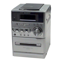
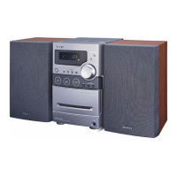
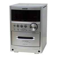
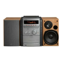
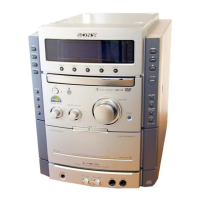
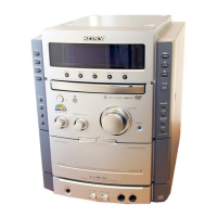
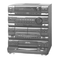
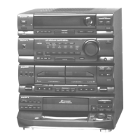
Identifies different model variations.

Handling Optical Pick-up Block

Precautions for handling the optical pick-up.

Laser Diode Emission Check

Procedures for checking laser diode output.

Laser Diode and Focus Search Check

Procedures for checking laser diode and focus.

Leading Flat Type Wires

Instructions for routing flat type wires.

General Information

Location of Controls

Identifies controls on the main unit and remote.

Setting the Clock

Procedure for setting the system clock.

Disassembly Procedures

Disassembly Flow Chart

Outlines the sequence for dismantling the unit.

Rear Cabinet Disassembly

Instructions for removing the rear cabinet.

Top Panel Assembly Disassembly

Instructions for removing the top panel.

Front Panel Assembly Disassembly

Instructions for removing the front panel.

Base Unit Disassembly

Instructions for removing the base unit.

Mechanical Deck Disassembly

Instructions for removing the mechanical deck.

Main Board Disassembly

Instructions for removing the main board.

Amplifier Board Disassembly

Instructions for removing the amplifier board.

Test Modes

Cold Reset Procedure

Clears stored data and resets the unit to initial conditions.

Panel Test Mode

Tests all segments of the LCD and displays system information.

Tuner Step Change-over

Selects AM channel step (9 kHz or 10 kHz).

Electrical Checks

Focus Bias Check

Verifies focus bias for optical block.

RF Signal Waveform Check

Observes eye pattern for AC range and sensitivity.

Diagrams

CD Servo Block Diagram

Illustrates the functional blocks of the CD servo system.

Main Section Block Diagram

Illustrates the functional blocks of the main system.

Printed Wiring Board & Schematic Notes

Guidelines for interpreting diagrams and boards.

CD Board Diagrams

Includes Printed Wiring and Schematic for the CD board.

Main Board Diagrams

Includes Printed Wiring and Schematics for the Main board.

AMP Section Diagrams

Includes Printed Wiring and Schematic for the Amplifier section.

Control Board Diagrams

Includes Printed Wiring and Schematic for the Control board.

Power Board Diagrams

Includes Printed Wiring and Schematic for the Power board.

Circuit Board Waveforms

Displays essential waveforms for various circuit boards.

IC Block Diagrams

Provides block diagrams for key integrated circuits.

IC301 Pin Function Description

Details the function of each pin for IC301.

IC303 Datasheet

Information on the BH15FB1WG integrated circuit.

IC801 Pin Function Description

Details the function of each pin for the System Controller.

Exploded Views

Panel Section Exploded View

Shows the assembly of the unit's external panels.

Front Panel Assembly-1 Exploded View

Details the components of the front panel assembly (part 1).

Front Panel Assembly-2 Exploded View

Details the components of the front panel assembly (part 2).

Top Panel Assembly Exploded View

Details the components of the top panel assembly.

Electrical Parts List

AMP Section Parts List

Lists components for the amplifier section.

CD Section Parts List

Lists components for the CD section.

Control Section Parts List

Lists components for the control section.

HP Section Parts List

Lists components for the HP section.

Main Section Parts List

Lists components for the main section.

Power Section Parts List

Lists components for the power section.

Revision History

Related product manuals