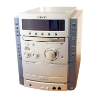
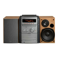
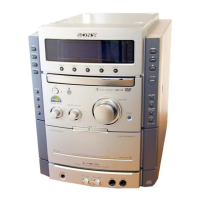
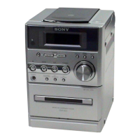
Do you have a question about the Sony HCD-NXM4D and is the answer not in the manual?
Precautions for handling the optical pick-up block and laser diode emission checks.
Test mode for checking segments, LEDs, microprocessor, keyboard, and display.
Test modes for amplifier and tape section functions, including equalizer and auto playback.
Sets DVD ship mode and performs a cold reset for shipping or customer return.
Instructions on how to enter and operate the test mode for diagnosis and adjustment.
Checks diagnostic items via serial interface, similar to board detail checks.
Automatically adjusts the drive mechanism for DVD-SL, CD, and DVD-DL discs.
Sets disc type and controls servo operations for replay.
Manages disc type settings and servo control for playback.
Adjusts EEPROM parameters and checks stored data.
Executes aging of the mechanism deck for testing.
Displays color bars for video level adjustment.
Precautions and torque measurements for mechanical adjustments.
Re-adjusts the servo circuit and checks video levels for proper operation.
Performs RFMON level check before optical pick-up exchange.
Block diagram illustrating the DVD DSP (1/2) section of the system.
Block diagram illustrating the DVD DSP (2/2) section of the system.
Block diagram showing the tuner and tape deck sections of the system.
Block diagram illustrating the main functional blocks of the system.
Block diagram detailing the amplifier sections of the system.
Electrical schematic of the RF board, showing component connections.
Electrical schematic of the DVD mechanism board, showing component connections.
Electrical schematic for the DMB07 board (1/6), showing component connections.
Electrical schematic for the DMB07 board (2/6), showing component connections.
Electrical schematic for the DMB07 board (3/6), showing component connections.
Electrical schematic for the DMB07 board (4/6), showing component connections.
Electrical schematic for the DMB07 board (5/6), showing component connections.
Electrical schematic for the DMB07 board (6/6), showing component connections.
Electrical schematic of the video board, detailing component connections.
Continued pin functions for the ZIVA5X-C2F IC on the DMB07 board.
Continued pin functions for the TMC57929PGF-RDP IC on the DMB07 board.
Continued pin functions for the CXP973064-245R IC on the DMB07 board.
Continued pin functions for the M3062CMEN-A01FPUO IC on the MAIN board.
| CD Player | Yes |
|---|---|
| FM Radio | Yes |
| USB Playback | Yes |
| Tuner Bands | FM |
| USB Port | Yes |
| Remote Control | Yes |
| Playable File Types | MP3 |
| Tuner | Yes |