EasyManua.ls Logo

Sony HCD-NXM2D User Manual

Sony HCD-NXM2D
102 pages
To Next Page IconTo Next Page
Page #1 background imageLoading...
Page #1 background image
HCD-NXM2D
E Model
SERVICE MANUAL
DISPLAY SIDE Hi-Fi COMPONENT SYSTEM
Sony Corporation
Home Audio Company
Published by Sony Engineering Corporation
9-877-968-01
2004F02-1
© 2004.06
SPECIFICATIONS
Ver 1.0 2004. 06
– Continued on next page –
HCD-NXM2D is the Amplifier, DVD player,
tape deck and tuner section in DHC-NXM2D.
Model Name Using Similar Mechanism NEW
DVD DVD Mechanism Type CDM81A-DVBU60
Section Base Unit Name DVBU60
Optical Pick-up Name DBU-3
TAPE
Model Name Using Similar Mechanism HCD-CPX22
Section
Main unit
Amplifier section
The following measured at AC 120, 127, 220, 240 V, 50/60 Hz
DIN power output (rated): 60 + 60 watts
(6 ohms at 1 kHz, DIN)
Continuous RMS power output (reference)
Front speaker: 75 + 75 watts
(6 ohms at 1 kHz, 10% THD)
Sub woofer: 120 watts
(4 ohms at 100 Hz, 10% THD)
Inputs
VIDEO/SAT IN (phono jacks):
voltage 250/450 mV, impedance 47
kilohms
MIC1/MIC2 (phone jacks): sensitivity 1 mV, impedance 10
kilohms
Outputs
VIDEO/SAT OUT (phono jacks):
voltage 250 mV, impedance 1 kilohm
VIDEO OUT (phono jack): max. output level
1 Vp-p, unbalanced, Sync
negative, load impedance
75 ohms
S VIDEO OUT (4-pin/mini-DIN jack):
Y: 1 Vp-p, unbalanced,
Sync negative,
C: 0.286 Vp-p, load
impedance 75 ohms
COMPONENT VIDEO OUT:
Y: 1 Vp-p, 75 ohms
PB, PR: 0.7 Vp-p, 75 ohms
DIGITAL OUT (Square optical connector jack, rear panel)
Wavelength: 660 nm
PHONES (stereo mini jack):
accepts headphones of
8 ohms or more
FRONT SPEAKER: Use only the supplied
speaker SS-NXM4D
SUB WOOFER SPEAKER:
Use only the supplied
speaker SS-WG4D
Disc player section
System Compact disc and digital
audio and video system
Laser Semiconductor laser

Table of Contents

Question and Answer IconNeed help?

Do you have a question about the Sony HCD-NXM2D and is the answer not in the manual?

Sony HCD-NXM2D Specifications

General IconGeneral
Speaker Type2-way
CD PlayerYes
FM TunerYes
BluetoothNo
USB PlaybackYes
MD PlayerYes
USB PortYes
MP3 PlaybackYes
Remote ControlYes
Speaker Configuration2.0
TypeMini System
FunctionsCD
TunerFM

Summary

SPECIFICATIONS

Amplifier, Inputs, and Outputs

Details amplifier performance, input/output specifications, and impedance.

Video, Audio, and Speaker Specifications

Specs for S VIDEO, COMPONENT VIDEO, DIGITAL OUT, PHONES, and speaker connection notes.

Disc Player Section Details

Information on the disc player system and laser.

SERVICING NOTES

Optical Pick-up and Laser Diode Handling

Precautions for handling optical pick-up and laser diode emission checks.

Mechanism Handling Notes

Service position for tape deck and CD/DVD mechanism exchange notes.

GENERAL INFORMATION

Locating Controls - Main Unit

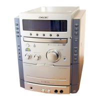
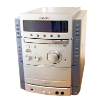
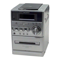
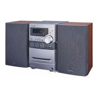
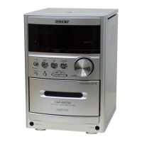
Identifies controls on the main unit and their functions.

Locating Controls - Remote Control

Identifies controls on the remote control and their functions.

DISASSEMBLY

Disassembly Flow

Outlines the sequence for disassembling the set.

External Chassis Components

Steps for removing the case and back panel.

DVD Section Disassembly

Steps for disassembling the DVD section.

Main and Front Panel Boards

Steps for removing the main and front panel boards.

TEST MODES

General Test Modes

Covers GC Test Mode and MC Test Modes for amplifier and tape sections.

DVD Control Modes

Procedures for DVD Ship Mode, power management, tray lock, and repeat limit.

System Diagnosis

Covers Syscon Diagnosis and related checks.

Drive Adjustments

Procedure for automatic adjustment of the drive system.

ADJUSTMENTS

Mechanical Adjustments

Procedures for mechanical adjustments and torque measurements.

Electrical Adjustments

Electrical adjustments for deck and video sections, including servo circuit.

DIAGRAMS

Circuit Board Locations

Visual guide to the location of all circuit boards within the unit.

Block Diagrams

Functional block diagrams illustrating signal flow for the DVD DSP section.

Printed Wiring Boards

Layout of components on the RF board.

Schematic Diagrams

Electrical schematic for the RF board.

EXPLODED VIEWS

External Chassis Views

Visual breakdown of the case and rear panel components.

Front Panel View

Visual breakdown of the front panel components.

Chassis Section View

Visual breakdown of the main chassis parts.

DVD Mechanism Views

Detailed part breakdown for the first section of the DVD mechanism.

ELECTRICAL PARTS LIST

Disc SW Board Components

List of capacitors, diodes, and resistors for the Disc SW board.

DMB07 Board Components

List of capacitors for the DMB07 board.

Front Amp Board Components

List of resistors and transistors for the Front Amp board.

HP Board Components

List of capacitors for the HP board.
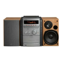
Related product manuals