Do you have a question about the Sony HCD-NEZ50 and is the answer not in the manual?
Procedures for safely handling the optical pick-up block and flexible circuit boards.
Method for visually checking the laser diode emission from the optical pick-up block.
Characteristics and handling precautions for unleaded solder used in the product.
Procedure to check laser diode emission and focus search operation.
Overview of fundamental operations like source selection, volume adjustment, and playback.
Steps for inserting and playing CD or MP3 discs, including track/folder selection.
How to tune into FM/AM radio stations and select stations using auto or manual tuning.
Instructions for inserting and playing cassette tapes.
How to change the display mode and understanding the information shown.
Guidance on connecting external audio devices to the system.
Creating custom CD programs, recording tapes, presetting radio stations, and using timer functions.
A step-by-step visual guide illustrating the order of disassembly for the unit.
Instructions and diagrams for removing the main cabinet and its top section.
Procedures for detaching the base unit and the front panel assembly.
Steps for disassembling the mechanical deck and the FM/AM tuner module.
Guidance on accessing and removing the main board and the FM/AM tuner.
How to perform a cold reset to clear initial settings and data.
Steps to test all segments of the liquid crystal display and view system version.
How to access and interpret CD error codes for troubleshooting.
Method to switch AM tuning steps between 9 kHz and 10 kHz.
Important safety and handling precautions before performing mechanical adjustments.
Specifications and methods for measuring torque on tape drive mechanisms.
How to measure and adjust tape tension for optimal performance.
Electrical adjustments related to the tape deck section, including head demagnetization.
Procedure for adjusting the azimuth of the record/playback head for optimal audio quality.
Procedure for checking and adjusting the focus bias of the CD player's optical pick-up.
Specific adjustments for the CD section, including focus bias and tracking bias checks.
A high-level overview of the CD servo system's signal paths and components.
A block diagram illustrating the main section's signal flow and interconnections.
Layout diagram of the CD board's component and conductor sides.
Detailed circuit schematic for the CD board.
Component and conductor side layouts for the main board.
First part of the main section's circuit schematic.
Second part of the main section's circuit schematic.
Layout diagrams for the panel board's component and conductor sides.
Detailed circuit schematic for the panel board.
Layout diagrams for the DC board's component and conductor sides.
Layout diagrams for the AC board's component and conductor sides.
Circuit schematic for the unit's power supply section.
Detailed pin functions for IC201 on the CD board.
Pin functions for various ICs across different boards, continuing from page 29.
An exploded view showing the parts and assembly of the main cabinet.
Exploded view detailing the front mechanical deck components.
Exploded view illustrating the panel board and its associated parts.
Exploded view for the top cabinet section, including pick-up block.
Exploded view showing the main board and its mounting components.
Exploded views for the AC and DC boards, showing transformers and spacers.
List of electrical components for the AC board.
List of electrical components for the Audio In board.
Comprehensive list of electrical components for the CD board.
List of electrical components for the Head Phone board.
List of electrical components for the Panel board.
| CD Player | Yes |
|---|---|
| Radio Tuner | FM/AM |
| Bluetooth | No |
| USB Playback | No |
| CD Changer | No |
| Remote Control | Yes |
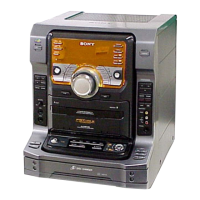
| Type | Mini Hi-Fi System |
| Power Output | 50W |
| Speaker Configuration | 2.0 Channel |