Do you have a question about the Sony HCD-N455KW and is the answer not in the manual?
Technical specifications for the HCD-N455KW audio system, covering various sections.
Guidelines for replacing chip components, emphasizing caution with specific parts.
Precautions and techniques for repairing flexible circuit boards, including soldering tips.
Precautions for handling the optical pick-up block to prevent electrostatic damage and physical damage.
Guidelines for checking the laser diode emission safely and correctly.
Procedure for checking laser diode and focus search operation using 'S curve check'.
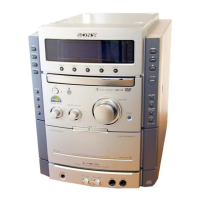
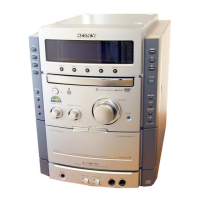
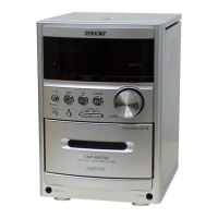
Identification of front panel controls and their corresponding page numbers for details.
Diagram showing amplifier section connections and controls.
Diagram showing rear panel terminals and their functions.
Diagram showing remote control buttons and their functions.
Diagram identifying indicators and displays on the unit's front panel.
Diagram identifying controls and compartments for the tape player section.
Diagram identifying controls and features for the CD player section.
Procedure for removing the front panel assembly and main board, including connector disconnection.
Procedure for disassembling the TC (Tape Cassette) mechanism deck.
Procedure for disassembling the CD mechanism deck.
Procedure for removing the BU (Base Unit) bracket assembly.
Procedure for installing and adjusting the disc table, including roller cam positioning.
Procedure for adjusting tape speed on Deck A, including test tape and equipment requirements.
Procedure for adjusting playback level for both Deck A and Deck B, specifying test tapes and settings.
Procedure for adjusting record bias on Deck B, including test modes and signal inputs.
Procedure for adjusting record level on Deck B, detailing playback signal confirmation and adjustment locations.
Procedure for adjusting the AM tuned level, specifying signal generator settings and adjustments.
Procedure for adjusting the FM tuned level, detailing signal input and tuning indicator adjustments.
Procedure for adjusting focus bias, including oscilloscope connection and waveform adjustments.
Procedure for performing an S-curve check on the CD player, including waveform symmetry confirmation.
Procedure for checking the RF signal level on the CD player, ensuring waveform clarity and correct level.
Procedure for checking E-F balance, ensuring symmetrical waveforms and level specifications.
Note regarding focus/tracking gain adjustment, indicating it may not require adjustment.
Block diagram illustrating the signal flow and major components within the tuner section.
Block diagram illustrating the signal flow and major components within the CD section, including optical pick-up.
Block diagram illustrating the signal flow and major components within the deck section, including playback and recording heads.
Block diagram illustrating the signal flow and major components within the main section, including power supply and control.
Detailed pin functions for IC701 (Master Control), a micro-controller unit.
Exploded view of the cabinet and back panel assembly, listing parts and hardware.
Exploded view of the panel board assembly, detailing various panel components and their locations.
Exploded view of the front panel section, identifying all buttons, indicators, and mechanical parts.
Exploded view of the chassis section, showing major structural components and their associated parts.
Exploded view of the first section of the TC mechanism, detailing cassette holder and lever assemblies.
Exploded view of the second section of the TC mechanism, showing springs, sliders, and head components.
Exploded view of the third section of the TC mechanism, illustrating cam, lever, and flywheel assemblies.
Exploded view of the CD mechanism, detailing gears, rollers, and the optical pick-up assembly.
Exploded view of the base unit section, showing the optical pick-up, motors, and gears.
List of capacitors with their part numbers, types, and specifications.
List of coils with their part numbers and specifications.
List of variable resistors with part numbers and resistance values.
List of transformers with part numbers and specifications.
List of Integrated Circuits (ICs) with their part numbers and designations.
List of motors with their part numbers and types.
List of transistors with their part numbers and designations.
List of resistors with part numbers, resistance, tolerance, and wattage.
List of switches with part numbers and their functions.
List of diodes with part numbers and types.
Information regarding the change of the TCB Board to a Tuner Pack assembly.
| Brand | Sony |
|---|---|
| Model | HCD-N455KW |
| Category | Stereo System |
| Language | English |