EasyManua.ls Logo

Sony HCD-LX5 User Manual

Sony HCD-LX5
62 pages
To Next Page IconTo Next Page
Page #1 background imageLoading...
Page #1 background image
SERVICE MANUAL
COMPACT Hi-Fi STEREO SYSTEM
US Model
HCD-LX30/LX50
Canadian Model
HCD-LX50
AEP Model
UK Model
HCD-LX5
E Model
Australian Model
HCD-LX6
SPECIFICATIONS
HCD-LX5/LX6/LX30/LX50
Photo: HCD-LX50
Dolby noise reduction manufactured under license
from Dolby Laboratories Licensing Corporation.
“DOLBY” and the double-D symbol ; are trade-
marks of Dolby Laboratories Licensing Corporation.
Model Name Using Similar Mechanism HCD-D290/G3300/XB3
CD Mechanism Type CDM37M-5BD32L
Base Unit Name BU-5BD32L
Optical Pick-up Name KSS-213D/Q-NP
Model Name Using Similar Mechanism HCD-DR4
Tape Transport Mechanism Type TCM-230PWR1
HCD-LX5/LX6/LX30/LX50 are the
Amplifier, CD player, Tape Deck and Tuner
section in LBT-LX5/LX6/LX30/LX50.
CD
Section
TAPE
Section
– Continued on next page –
Question and Answer IconNeed help?

Do you have a question about the Sony HCD-LX5 and is the answer not in the manual?

Sony HCD-LX5 Specifications

General IconGeneral
CD PlayerYes
BluetoothNo
USB PlaybackNo
Speaker Configuration2.0
Remote ControlYes
TypeMini Hi-Fi System
Radio TunerAM/FM
FunctionsCD, Radio

Summary

SPECIFICATIONS

AUDIO POWER SPECIFICATIONS

Details on power output and total harmonic distortion for the amplifier section.

CD, TAPE, TUNER, AND GENERAL SPECIFICATIONS

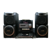
Technical details for CD, tape, tuner functions, and general system information like power requirements and dimensions.

SERVICING AND SAFETY GUIDELINES

SAFETY CHECK-OUT AND LEAKAGE TEST PROCEDURES

Instructions for performing safety checks, including AC leakage testing after repairs.

GENERAL PRECAUTIONS AND HANDLING NOTES

Notes on laser safety, component handling, and circuit board repair precautions.

SYSTEM LAYOUT AND SETUP PROCEDURES

FRONT PANEL CONTROL LAYOUT AND IDENTIFICATION

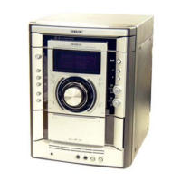
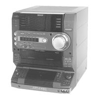
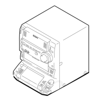
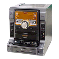
Diagram identifying all front panel controls, buttons, and connectors.

CLOCK SETTING PROCEDURE

Step-by-step guide for setting the system's internal clock.

DISASSEMBLY AND SCHEMATIC DIAGRAMS

DISASSEMBLY STEPS FOR EXTERNAL AND INTERNAL COMPONENTS

Sequential instructions for taking apart the unit's external and internal components.

CIRCUIT BOARD LOCATIONS AND DETAILED DIAGRAMS

Overview of board locations, followed by detailed PWB and schematic diagrams for major sections.

EXPLODED VIEWS AND PARTS LIST

EXPLODED VIEWS OF ASSEMBLY COMPONENTS

Illustrated diagrams showing the assembly of various parts and mechanisms.

COMPREHENSIVE ELECTRICAL PARTS LIST

Detailed list of all electrical components with part numbers, descriptions, and specifications.

Related product manuals