Do you have a question about the Sony HCD-LV100AV and is the answer not in the manual?
Details power output, sensitivity, and impedance for front, center, and rear speakers.
Specifications for video inputs and outputs, including signal levels and impedance.
Technical specifications for the CD/DVD player, including laser type and response.
Electrical requirements, power consumption, and physical dimensions of the unit.
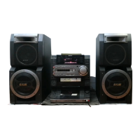
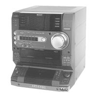
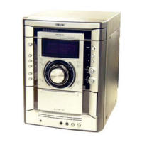
Information for identifying the model based on the back panel label.
Steps to ensure safety and proper function after service or repair.
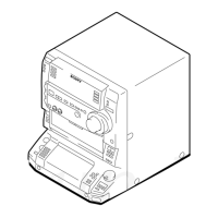
Step-by-step instructions for removing the upper case of the unit.
Procedures for disassembling the front panel section, detailing connections and screws.
Procedure to clear all preset data and reset the unit to initial conditions.
Mode to move the CD pick-up to a stable position for shipping or handling.
Mode to operate the CD sled motor freely for cleaning or adjustment.
Mode where all LEDs and the indicator tube illuminate for display and key check.
Table specifying torque values for various tape mechanism adjustments.
Procedures for demagnetizing heads, applying locking compound, and setting power voltage.
Steps to adjust the azimuth for optimal playback head alignment.
Procedure for adjusting tape speed for both decks using test tapes and a frequency counter.
Steps to adjust playback levels for L-CH and R-CH for both decks.
Procedure to check the symmetry and peak-to-peak level of the S-curve waveform.
Procedure to check the E-F balance and DC voltage using a 1-track jump mode.
Procedure to confirm RF signal waveform clarity and correct level.
Procedure to adjust the video board frequency to 27.0 MHz at stop status.
Diagram showing the physical layout and names of all circuit boards in the unit.
High-level block diagram illustrating the signal flow for tuner, CD, and deck sections.
Displays various waveforms from the VIDEO board for analysis and troubleshooting.
Illustrates key waveforms from the BD board, essential for CD player diagnostics.
Shows critical waveforms from the MAIN board for system checks.
Displays waveforms related to the front panel controls and display functions.
Visual representation of the BD board IC functions and interconnections.
Block diagrams for key ICs on the MAIN board, showing their internal logic.
Block diagrams for ICs on the PANEL FL board, detailing control functions.
Functional block diagrams for ICs within the VIDEO section.
Detailed pin function description for IC501 on the MAIN board.
Pinout and function description for IC601 on the PANEL FL board.
Pin function details for IC502, the CD mechanism controller.
Pin function description for IC505, the MPEG decoder and video processor.
Exploded view of the unit's case and back panel, showing assembly components.
Exploded view of the front panel, detailing parts like boards, levers, and knobs.
Exploded view of the front panel assembly, including wires and levers.
Exploded view of the main chassis and related boards, including transformers and feet.
Exploded view of the tape mechanism deck, showing heads, pinch levers, and bases.
Exploded view of the tape mechanism, detailing belts, motors, and springs.
Exploded view of the CD mechanism, showing screws, gears, motors, and boards.
Exploded view of the base unit, illustrating optical pick-up, motors, and boards.
List of screws, wires, and other hardware components used in the unit's assembly.
| Type | Stereo System |
|---|---|
| Power Output | 100W |
| Audio Channels | 2.0 |
| CD Player | Yes |
| Tuner | Yes |
| Radio | AM/FM |
| USB Port | No |
| MP3 Playback | Yes |
| Remote Control | Yes |
| Cassette Deck | Yes |
| Weight | Not found |
| Output Power | 100W |