EasyManua.ls Logo

Sony HCD-LV80 User Manual

Sony HCD-LV80
92 pages
To Next Page IconTo Next Page
Page #1 background imageLoading...
Page #1 background image
1
HCD-LV80
E Model
SPECIFICATIONS
COMPACT Hi-Fi STEREO SYSTEM
— Continued on next page —
Model Name Using Similar Mechanism HCD-VR50/VR70
CD Mechanism Type CDM37L-5BD34L
Base Unit Type BU-5BD34L
Optical Pick-up Type KSS-213D/Q-NP
Model Name Using Similar Mechanism NEW
Tape Transport Mechanism Type TCM-230PWR12
CD
SECTION
TAPE DECK
SECTION
SERVICE MANUAL
HCD-LV80 is the tuner, deck, CD and
amplifier section in LBT-LV80.
Amplifier section
The following measured at AC 120/220/240 V,
50/60 Hz
DIN power output (Rated)
240 + 240 watts
(4 ohms at 1 kHz, DIN)
Continuous RMS power output (Reference)
300 + 300 watts
(4 ohms at 1 kHz, 10 %
THD)
Inputs
PHONO IN (phono jacks): sensitivity 3 mV,
impedance 47 kilohms
MIC 1/2 (phono jack): sensitivity 1 mV,
impedance 10 kilohms
VIDEO 1 IN (phono jacks):sensitivity 250 mV,
impedance 47 kilohms
VIDEO 2 IN (phono jacks):sensitivity 250 mV,
impedance 47 kilohms
MD IN (phono jacks): sensitivity 450 mV,
impedance 47 kilohms
Outputs
PHONES (stereo phone jack):
accepts headphones of
8 ohms or more
VIDEO OUT (phono jack): voltage 250 mV,
impedance 1 kilohm
MD OUT (phono jacks): voltage 250 mV,
impedance 1 kilohm
FRONT SPEAKER :
accepts impedance of 4 to
16 ohms
Video section
Inputs
VIDEO1 IN (phono jacks): 1 V p-p, 75 ohms
VIDEO2 IN (phono jacks): 1 V p-p, 75 ohms
Outputs
VIDEO OUT (phono jack):1 V p-p, 75 ohms
S-VIDEO OUT (4-pin/mini-DIN jack):
Y: 1 V p-p, unbalanced,
Sync negative,
C: 0.286 V p-p,
load impedance 75 ohms
VIDEO CD/CD player section
System Compact disc, digital
audio and video system
Laser Semiconductor laser
(λ = 780 ohm), Emission
duration : continuous
Laser output Max. 44.6 µW*
* This output is the value
measured at a distance of
200 mm from the
objective lens surface on
the Optical Pick-up Block
with 7 mm aperture.
Wavelength 780 - 790 nm
Fre
q
uenc
y
Res
p
onse 2 Hz - 20 kHz
(
±0.5 dB
)
Signal-to-noise ratio More than 90 dB
Dynamic range More than 90 dB
CD DIGITAL OUT
(square optical connector jack, rear panel)
Video color system format
NTSC, PAL
Wave length: 660 nm
Output level: –18 dBm
Tape player section
Recording system 4-track 2-channel stereo
Frequency Response (DOLBY NR OFF)
40 - 13,000 Hz (±3 dB),
using a Sony TYPE I
cassette
40 - 14,000 Hz (±3 dB),
using a Sony TYPE II
cassette

Table of Contents

Question and Answer IconNeed help?

Do you have a question about the Sony HCD-LV80 and is the answer not in the manual?

Sony HCD-LV80 Specifications

General IconGeneral
BrandSony
ModelHCD-LV80
CategoryStereo System
LanguageEnglish

Summary

SPECIFICATIONS

Amplifier section

Detailed electrical and input/output specifications for the amplifier.

Video section

Specifications for the video input/output signals and formats.

VIDEO CD/CD player section

Technical specifications for the CD playback system and laser.

Tape player section

Specifications for the tape deck's recording and playback capabilities.

Tuner section

FM tuner section

Tuning range, antenna specifications, and intermediate frequency for FM reception.

AM tuner section

Tuning range and intermediate frequency for AM reception.

MODEL IDENTIFICATION

NOTES ON HANDLING THE OPTICAL PICK-UP BLOCK OR BASE UNIT

Guidelines for safely handling sensitive optical pick-up components during repair.

NOTES ON LASER DIODE EMISSION CHECK

Precautions for checking laser diode emission safely and correctly.

SECTION 1 SERVICING NOTE

MC Cold Reset

Procedure to clear all stored data and reset the unit to initial conditions.

CD Delivery Mode

Procedure to move the CD pick-up to a position suitable for transport.

Sled Servo Mode

Mode to freely run the CD sled motor, useful for cleaning the pick-up.

LED and Fluorescent Indicator Tube All Lit, Key Check Mode

Mode to test all LEDs and fluorescent indicators, and check button functions.

SECTION 2 GENERAL

LOCATION OF PARTS AND CONTROLS

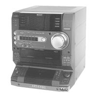
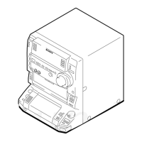
Identification and description of all buttons, knobs, jacks, and indicators on the front panel.

SECTION 3 DISASSEMBLY

3-1. FRONT PANEL AND VIDEO BOARD

Step-by-step guide for removing the front panel and video board assembly.

3-2. MAIN BOARD

Procedure for disassembling and accessing the main circuit board.

3-3. SUB PANEL

Steps to remove the sub panel, revealing internal components.

3-4. CD LID ASSEMBLY

Guide for disassembling the CD lid and its related parts.

3-5. TAPE MECHANISM DECK AND CASSETTE LID

Procedure for dismantling the tape deck mechanism and cassette lid.

SECTION 4 TEST MODE

VIDEO CD COLOR-BARS MODE

Test mode for checking video CD signals with color bars and audio output.

SECTION 5 MECHANICAL ADJUSTMENTS

Torque Measurement

Specifications and methods for measuring torque on various mechanical parts.

SECTION 6 ELECTRICAL ADJUSTMENTS

Record/Playback Head Azimuth Adjustment (Deck A, Deck B)

Procedure for adjusting the record/playback head azimuth for optimal stereo separation.

Tape Speed Adjustment (Deck A)

Steps to adjust tape speed for both normal and double-speed playback.

Record Bias Adjustment (Deck B)

Procedure for adjusting the record bias level for tape recording accuracy.

CD SECTION

S Curve Check

Procedure for checking the S-curve waveform related to focus and tracking servo performance.

E-F Balance (Traverse) Check

Method for checking the traverse balance of the optical pick-up.

RF Level Check

Procedure to verify the RF signal level from the CD player.

SECTION 7 DIAGRAMS

7-1. CIRCUIT BOARDS LOCATION

Diagram illustrating the physical placement of all circuit boards within the unit.

7-2. Block Diagrams

High-level block diagrams showing system architecture and signal flow.

SECTION 8 EXPLODED VIEWS

8-1. CASE AND BACK PANEL SECTION

Exploded view showing the main chassis, back panel, and associated hardware.

8-2. FRONT PANEL SECTION 1

Exploded view of the front panel components, including controls and indicators.

8-3. FRONT PANEL SECTION 2

Further exploded view of front panel parts, such as CD lid and panel assemblies.

8-4. CHASSIS SECTION

Exploded view of the internal chassis structure and major component mounting.

8-5. TC MECHANISM SECTION 1 (TCM230PWR12)

Exploded view of the tape mechanism (Deck A) components.

8-6. TC MECHANISM SECTION 2 (TCM230PWR12)

Exploded view of the tape mechanism (Deck B) components and related parts.

8-7. CD MECHANISM SECTION (CDM37L-5BD34L)

Exploded view of the CD player mechanism assembly.

8-8. BASE UNIT SECTION (BU-5BD34L)

Exploded view of the base unit, including optical pick-up and motor.

SECTION 9 ELECTRICAL PARTS LIST

AUDIO

List of electrical components used in the audio section of the main board.

BD

List of components for the BD (Base Unit) board, including resistors, capacitors, and ICs.

MAIN

Comprehensive list of components for the main board, covering various sections.

VIDEO

List of electrical components used in the video processing sections.

MISCELLANEOUS

Listing of general parts, wires, fuses, and hardware used in the assembly.

MISCELLANEOUS

HARDWARE LIST

A detailed list of screws, wires, and other hardware used in the product.

Related product manuals