Do you have a question about the Sony HCD-L1 and is the answer not in the manual?
Details of audio power, inputs, outputs, CD player, and tuner sections.
Precautions for handling the optical pick-up block and laser diode emission.
Guidelines for replacing chip components and circuit board repair.
Index of buttons and parts with their corresponding illustration and reference pages.
Details on remote control button operations, battery replacement, and clock setting.
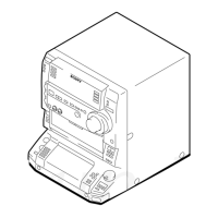
Instructions for removing the case, front panel, and door panel assemblies.
Steps for disassembling main internal boards, CD mechanism, motors, and sensors.
Modes for keyboard check, amplifier test, version display, and FL tube segment test.
Modes for forced reset, CD ship position, aging operation, and error history display.
Procedures for RF level and E-F balance checks in the CD section.
Block diagrams for CD/Main sections and circuit board location overview.
Schematic and printed wiring board diagrams for BD, CD, and Motor sections.
Schematic and printed wiring board diagrams for Main and AMP sections.
Schematic and printed wiring board diagrams for Display, Switch, and Power sections.
IC block diagrams, waveforms, and detailed IC pin function descriptions.
Exploded views of the case, chassis, and front panel sections.
Exploded views of the CD mechanism and base unit components.
Comprehensive list of electrical components with part numbers and specifications.
| CD Player | Yes |
|---|---|
| CD Player Type | Single Disc |
| Tuner | FM/AM |
| Bluetooth | No |
| USB Port | No |
| Weight | 3.5 kg |
| Remote Control | Yes |
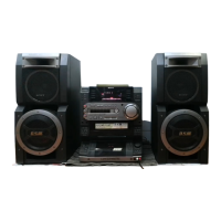
| Speaker Type | 2-way |
| Cassette Deck | Yes |