Do you have a question about the Sony HCD-LV60 and is the answer not in the manual?
Technical specifications for the CD playback mechanism.
Technical specifications for the tape deck mechanism.
Power output and input/output specifications for the amplifier.
Specifications related to laser and CD digital output for the player.
Specifications for video inputs and outputs.
General information including control locations and time setting.
Procedures and instructions for disassembling the unit.
Procedures for entering and utilizing various test modes for diagnostics.
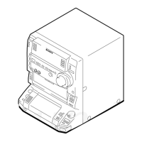
Visual representation of the unit's parts for identification and replacement.
A comprehensive list of electronic components used in the unit.
Identifies the location of all controls on the front panel.
Instructions for setting the system's clock time.
Details the self-diagnosis function for diagnosing VIDEO board circuit conditions.
Precautions for handling the optical pick-up to prevent electrostatic damage.
Guidelines for safely checking laser diode emission from the optical pick-up.
Procedure for checking laser diode and focus search waveforms.
Important notes regarding the replacement of chip components, especially tantalum capacitors.
Recommendations for repairing flexible circuit boards, including soldering iron temperature.
Identifies the location of all controls on the front panel.
Instructions for disassembling the outer case of the unit.
Instructions for disassembling the front panel assembly.
Clears all data and resets the unit to initial conditions.
Resets the unit while retaining preset data, similar to power cycling.
Procedure to switch the AM tuning interval between 9 kHz and 10 kHz.
Moves the optical pick-up to a vibration-durable position for shipping.
Activates all LEDs and the display for key check functionality.
Mode for operational check of the tape deck section working in parallel.
Describes the sequence of operations for the tape deck aging mode.
Contains block diagrams, printed wiring boards, and schematic diagrams for system analysis.
Diagram illustrating the CD servo control system architecture.
Diagram showing the signal flow for audio and video in the CD section.
Diagram outlining the tape deck's operational blocks and signal paths.
Diagram detailing the primary functional blocks of the main unit.
Diagram showing the display, key controls, and power supply interconnections.
General precautions to follow before performing mechanical adjustments.
Table detailing modes, torque meter, and meter readings for adjustments.
Adjustments specific to the tape deck section.
General precautions for electrical adjustments.
Lists test tapes and their usage for adjustments like azimuth and speed.
Procedure for adjusting the azimuth of record/playback heads for both decks.
Procedure for adjusting the tape speed using specific test tapes.
Procedure for adjusting the playback signal level for both decks.
Procedure for adjusting the recording bias level for Deck B.
Procedure for adjusting the recording signal level for Deck B.
Procedure to check the S-curve waveform for CD playback.
Checks the E-F balance and 1-track jump waveform for CD playback.
Procedure for adjusting the frequency of the CD player's video section.
Procedure to check the RF signal level waveform for CD playback.
Explains symbols and conventions used on the printed wiring board diagrams.
Explains symbols, component values, and conventions used in schematic diagrams.
Illustrates the physical location of various circuit boards within the unit.
Block diagram for the CXD3008Q IC used in the BD board.
Block diagram for the CXA2568M-T6 IC used in the BD board.
Block diagram for the NJM2267M IC in the VIDEO board, showing amplifier functions.
Block diagram for the TA8409S IC in the CD MOTOR board, illustrating driver functions.
Block diagram for the μPC1330HA IC in the AUDIO board, showing comparator functions.
Block diagram for the MC14052BF IC in the MAIN board, showing analog switch functions.
Block diagram for the BA3830F IC in the PANEL FL board, detailing filter and detector functions.
Block diagram for the M65850P IC in the MIC board, showing digital echo functions.
Block diagram for the CXD3008Q IC, detailing its internal functions.
Block diagram for the CXA2568M-T6 IC, showing its signal paths and blocks.
Block diagram for the NJM2267M IC in the VIDEO board, showing amplifier functions.
Block diagram for the TA8409S IC in the CD MOTOR board, illustrating driver functions.
Block diagram for the μPC1330HA IC in the AUDIO board, showing comparator functions.
Block diagram for the MC14052BF IC in the MAIN board, showing analog switch functions.
Block diagram for the BA3830F IC in the PANEL FL board, detailing filter and detector functions.
Block diagram for the M65850P IC in the MIC board, showing digital echo functions.
| Tuner | FM/AM |
|---|---|
| Bluetooth | Yes |
| USB Playback | Yes |
| CD Player Type | Single Disc |
| Remote Control | Yes |
| Type | Mini Hi-Fi Component System |
| Disc Compatibility | CD, CD-R/RW |
| Functions | CD, USB, Bluetooth, FM/AM Radio |