Do you have a question about the Sony HCD-LX10AV and is the answer not in the manual?
Essential safety checks, including AC leakage testing, after servicing.
Guidelines for handling optical pick-ups, chip components, and flexible circuits.
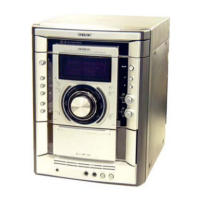
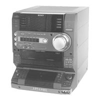
Identification and function of all controls and displays on the front panel.
Description of all input/output jacks and terminals on the rear panel.
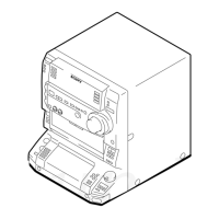
Steps for removing the unit's upper case and front panel assembly.
Procedures for dismantling tape and CD mechanism decks.
Instructions for disassembling the CD base unit and disc table.
Details on cold reset, CD delivery, sled servo, and tuner step modes.
Procedures for AMS test, aging sequences, and error history display.
Procedures for mechanical adjustments and torque measurement specifications.
Steps for electrical adjustments like head azimuth, tape speed, and levels.
Procedures for adjusting record bias and playback levels on the tape deck.
Visual guide to PCB layout and overall system signal flow.
Detailed component layout diagrams for all major circuit boards.
Comprehensive electrical schematics for detailed circuit analysis.
Internal IC schematics and pinout information for troubleshooting.
| CD Player | Yes |
|---|---|
| Disc Compatibility | CD, CD-R, CD-RW |
| Tuner | AM/FM |
| Bluetooth | No |
| USB Port | No |
| Cassette Deck | Yes |
| Remote Control | Yes |
| Audio Channels | 2.0 |
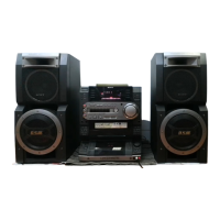
| Type | Mini Hi-Fi System |