EasyManua.ls Logo

Sony HCD-LX9AV User Manual

Sony HCD-LX9AV
82 pages
To Next Page IconTo Next Page
Page #1 background imageLoading...
Page #1 background image
HCD-LX9AV/LX10AV/LX90AV
US Model
HCD-LX90AV
AEP Model
UK Model
HCD-LX9AV
E Model
Australian Model
HCD-LX10AV
SERVICE MANUAL
COMPACT HI-FI STEREO SYSTEM
Dolby noise reduction manufactured under license
from Dolby Laboratories Licensing Corporation.
“DOLBY” and the double-D symbol ; are trade-
marks of Dolby Laboratories Licensing Corporation.
Model Name Using Similar Mechanism HCD-DR8AV/
W900AV
CD
CD Mechanism Type CDM37M-5BD32L
Section
Base Unit Name BU-5BD32L
Optical Pick-up Name KSS-213D/Q-NP
Model Name Using Similar Mechanism HCD-DR8AV/
Tape deck
W900AV
Section
Tape Transport Mechanism Type TCM-230PWR1
HCD-LX9AV/LX10AV/LX90AV are the
Amplifier, CD player, Tape Deck adn Tuner
section in LBT-LX9AV/LX10AV/LX90AV
— Continued on next page —
SPECIFICATIONS
Photo: HCD-LX9AV
Sony Corporation
Home Audio Company
Published by Sony Engineering Corporation
9-929-201-12
2002F1600-1
© 2002.06
Ver 1.1 2002. 06
Question and Answer IconNeed help?

Do you have a question about the Sony HCD-LX9AV and is the answer not in the manual?

Sony HCD-LX9AV Specifications

General IconGeneral
TypeStereo System
Total Power Output120 W
CD PlayerYes
BluetoothNo
USB PlaybackNo
Speakers2 Speakers + Subwoofer
Cassette DeckYes
Radio TunerFM/AM
FunctionsCD, Radio, Cassette
Output Power60 W
TunerFM/AM
Amplifier Output Power50W + 50W

Summary

Service Manual Overview

Specifications

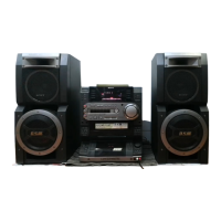
Details about audio power output, speaker specifications, and tuner sections.

Service Notes and Safety

Safety Checks and Leakage

Procedures for checking AC leakage on exposed metal parts to ensure safety.

Laser Product Safety

Precautions for handling optical pick-up blocks and checking laser diode emission.

Unit Controls and Disassembly

Location of Controls (Front & Rear Panel)

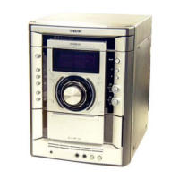
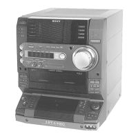
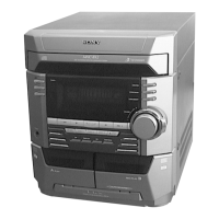
Identifies and describes the controls and connections on the front and rear panels.

Disassembly Procedures

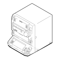
Step-by-step guides for disassembling major sections like upper case, front panel, and mechanisms.

Service Modes and Adjustments

Service Mode Functions

Describes various service modes like resets, test modes, and key checks.

Mechanical and Electrical Adjustments

Details procedures for mechanical adjustments and electrical adjustments like head azimuth and tape speed.

Technical Diagrams

Circuit Board Locations, Block Diagrams, and Schematics

Identifies circuit board locations, presents block diagrams, and schematic diagrams for unit sections.

Printed Wiring Boards

Layouts of printed wiring boards for different sections, showing component placement.

IC Block Diagrams and Pin Functions

Block diagrams for ICs and pin function descriptions for key integrated circuits.

Exploded Views

Electrical Parts List

Revision History

Related product manuals