EasyManua.ls Logo

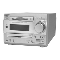
Sony HCD-MC1 User Manual

Sony HCD-MC1
80 pages
To Next Page IconTo Next Page
Page #1 background imageLoading...
Page #1 background image
HCD-MC1
US Model
E Model
SERVICE MANUAL
MINI HI-FI COMPONENT SYSTEM
Manufactured under license from Dolby Laboratories
Licensing Corporation.
“DOLBY” and the double-D symbol a are trademarks
of Dolby Laboratories Licensing Corporation.
— Continued on next page —
SPECIFICATIONS
This set is the tuner, deck, CD
and amplifier section in MHC-MC1.
Model Name Using Similar Mechanism HCD-F150/FR10
CD Mechanism Type CDM-46B1
Optical Pick-up Name KSS-213BA/F-NP
Model Name Using Similar Mechanism HCD-DR8AV
Tape Transport Mechanism Type TCM-230AWR2/230PWR2
CD
Section
Tape deck
Section
Sony Corporation
Home Audio Company
Published by Sony Engineering Corporation
9-928-899-12
2001J1600-1
© 2001.10
Amplifier section
U.S.A models:
AUDIO POWER SPECIFICATIONS
POWER OUTPUT AND TOTAL HARMONIC DISTORTION:
With 8 loads both channels driven, from 70 – 20,000 Hz; rated 80 W per
channel minimum RMS power, with no more than 0.9% toral harmonic
distortion from 250 mW to read output.
Continuous RMS power output
80 + 80 W(8 at 1kHz, 10% THD)
Tortal harmonic distortion
less than 0.09%(8 at 1kHz, 40W)
Inputs
VIDEO/MD IN (phono jack):
voltage 250mV/450mV,
impedance 47k
Outputs
VIDEO/MD OUT (phono jack):
voltage 250mV,
impedance 1k
PHONES (stereo phone jacks):
accepts headphones of 8 or more
SPEAKER : accepts impedance of 8 to 16
REAR SPEAKER :
accepts impedance of 16
SUPER WOOFER :
Voltage 1V, impedance 1k
CD player section
System Compact disc and digital audio system
Laser Semiconductor laser (λ =780mm)
Emission duration:
continuous
Laser output Max. 44.6µW*
*This output is the value measured at a distance of
200 mm from the objective lens surface on the
Optical Pick-up Block with 7 mm aperture.
Frequency response 2Hz – 20kHz (±0.5dB)
Wavelength 780 – 790nm
Signal-to-noise retio More than 90dB
Dynamic range More than 90dB
CD OPTICAL DIGITAL OUT
(Square optical connector jack, rear panel)
Output Level –18dBm
Tape player section
Recording system 4-track 2-channel stereo
Frequency response (DOLBY NR OFF)
40 – 13,000Hz (±3dB),
using Sony TYPE I
cassette
40 – 14,000Hz (±3dB),
using Sony TYPE II
cassette
Tuner section
FM stereo, FM/AM superheterodyne tuner
FM tuner section
Tuning range 87.5 – 108.0MHz
Antenna FM lead antenna
Antenna terminals 75 unbalanced
Intermediate frequency 10.7MHz
Ver 1.1 2001. 10
Question and Answer IconNeed help?

Do you have a question about the Sony HCD-MC1 and is the answer not in the manual?

Sony HCD-MC1 Specifications

General IconGeneral
CD PlayerYes
TunerFM/AM
BluetoothNo
USB PlaybackYes
Cassette PlaybackYes
Remote ControlYes
TypeMini Hi-Fi System
Speakers2 speakers included

Summary

Specifications

Laser Output Specifications

Technical details on laser output power and aperture dimensions.

Tape Player Specifications

Specifications for the tape deck, including frequency response and cassette type.

Tuner Section Specifications

Specifications for the FM/AM superheterodyne tuner, including tuning range.

Amplifier Section Specifications

Audio Power Output and Distortion

Power output and total harmonic distortion details for US models.

General Specifications

Power Requirements and Consumption

Unit requirements, physical specs, and included items.

Dimensions, Mass, and Accessories

Unit requirements, physical specs, and included items.

Safety Precautions and Warnings

Safety Check-Out and AC Leakage

AC leakage measurement and safety checks for US models.

Component Warning

Warning about critical components identified by mark for safety.

Servicing Notes

Handling Optical Pick-up and Laser Diode

Precautions for handling optical pick-up, laser diode emission, and chip components.

Circuit Board Repair Guidelines

Guidelines for flexible circuit board repair, including soldering temperature and conductor care.

Front Panel Overview

Front Panel Controls and Indicators

Identification and function of buttons, knobs, and indicators on the front panel.

Rear Panel Overview

Rear Panel Connections and Terminals

Identification of input/output jacks and terminals on the rear panel.

Disassembly Procedures

Case, Front Panel, and Door Assembly Disassembly

Steps for removing case, front panel, and door assembly.

Disassembly Procedures

Back Panel, Main Board, Power Transformer, and Sub Chassis Disassembly

Steps for removing back panel, main board, power transformer, and sub chassis.

Disassembly Procedures

CD Mechanism, Base Unit, Tape Mechanism, and Panel Board Disassembly

Steps for removing CD mechanism, base unit, tape mechanism, and panel board.

Disassembly Procedures

BD Board, Sled Motor, and Optical Pick-up Disassembly

Steps for removing BD board, sled motor, and optical pick-up.

Disassembly Procedures

Audio Board and Capstan Motor Disassembly

Steps for removing audio board and capstan motor.

Test Modes

MC Reset, CD Tests, GC Mode, and MC Test Mode

Procedures for various test modes including resets, CD tests, GC, and MC modes.

Advanced Test Modes

Aging, Function Change, and AM Tuner Step Selection Modes

Procedures for Aging, Function Change, and AM Tuner Step Selection modes.

Mechanical Adjustments

Tape Mechanism and Disc Sensor Adjustments

Procedures for tape mechanism torque and disc sensor alignment.

Mechanical Assembly Alignments

Magnet and Disc Holder Alignments

Procedures for aligning magnet assembly and disc holder.

Electrical Adjustments

Deck Section Azimuth Adjustment

Procedure for record/playback head azimuth adjustment on decks.

Tape Deck Electrical Adjustments

Tape Speed, Bias, Level, and Playback Adjustments

Procedures for tape speed, bias, level, and playback adjustments on tape decks.

CD Section Adjustments

S Curve, RF Level, and E-F Balance Checks

Procedures for S curve, RF level, and E-F balance checks on CD section.

CD RF PLL Adjustment

Diagrams Overview

CD Section Block Diagram

Block diagram illustrating the signal flow and components of the CD section.

Main Section Block Diagram

Audio Section Block Diagram

Circuit Board Locations

Printed Wiring Boards

BD Section Printed Wiring Board

Printed wiring board layout for the BD section, showing component placement.

Schematic Diagrams

BD Section Schematic Diagram

Schematic diagram detailing the electrical connections and components of the BD section.

Printed Wiring Boards

CD Motor Section Printed Wiring Board

Printed wiring board layout for the CD motor section.

Schematic Diagrams

CD Motor Section Schematic Diagram

Schematic diagram for the CD motor section, showing its electrical circuits.

Printed Wiring Boards

Audio Section Printed Wiring Board

Printed wiring board layout for the audio section, detailing component placement.

Schematic Diagrams

Audio Section Schematic Diagram

Schematic diagram illustrating the audio section's circuitry and connections.

Printed Wiring Boards

Leaf SW Section Printed Wiring Board

Printed wiring board layout for the leaf switch section.

Schematic Diagrams

Leaf SW Section Schematic Diagram

Schematic diagram for the leaf switch section, showing its electrical configuration.

Printed Wiring Boards

Main Section Printed Wiring Board

Printed wiring board layout for the main section of the unit.

Schematic Diagrams

Main Section Schematic Diagram (1/5)

First part of the main section schematic.

Schematic Diagrams

Main Section Schematic Diagram (2/5)

Second part of the main section schematic.

Schematic Diagrams

Main Section Schematic Diagram (3/5)

Third part of the main section schematic.

Schematic Diagrams

Main Section Schematic Diagram (4/5)

Fourth part of the main section schematic.

Schematic Diagrams

Main Section Schematic Diagram (5/5)

Fifth part of the main section schematic.

Printed Wiring Boards

Panel Section Printed Wiring Board

Printed wiring board layout for the Panel section.

Schematic Diagrams

Panel Section Schematic Diagram

Schematic diagram for the Panel section.

Printed Wiring Boards

Power Section Printed Wiring Board

Printed wiring board layout for the Power section.

Schematic Diagrams

Power Section Schematic Diagram

Schematic diagram for the Power section.

Waveforms and IC Pin Functions

BD Board IC101 Waveforms and Pin Functions

Waveforms and pinout for BD board IC101.

Panel Section Waveforms

Oscilloscope waveforms for panel section ICs.

IC Pin Function Descriptions

BD Board IC102 Pin Functions

Pinout and function description for BD board IC102.

IC Pin Function Descriptions

BD Board IC102 Pin Functions (Continued)

Continued pinout and function description for BD board IC102.

IC Pin Function Descriptions

Main Board IC501 Pin Functions

Pinout and function description for main board IC501.

IC Pin Function Descriptions

Main Board IC401 Pin Functions

Pinout and function description for main board IC401.

IC Pin Function Descriptions

Main Board IC501 Pin Functions

Pinout and function description for main board IC501.

IC Pin Function Descriptions

Main Board IC501 Pin Functions (Continued)

Continued pinout and function description for main board IC501.

IC Pin Function Descriptions

Panel Board IC601 Pin Functions

Pinout and function description for panel board IC601.

IC Block Diagrams

Panel Board IC Block Diagram

Block diagram for IC603 on the panel board.

Main/Audio Board IC Block Diagrams

Block diagrams for IC461, IC602, and IC701.

Exploded Views Overview

Case Section Exploded View

Exploded view of the case section, showing parts and their assembly.

Front Panel Section Exploded View

Chassis Section Exploded View

CD Mechanism Deck Section-1 Exploded View

CD Mechanism Deck Section-2 Exploded View

Optical Pick-up Section Exploded View

Tape Mechanism Deck Section-1 Exploded View

Tape Mechanism Deck Section-2 Exploded View

Electrical Parts List

Audio and BD Board Parts List

List of electrical parts for the Audio and BD boards.

Electrical Parts List

BD, CD Door, CD LED, CD Motor, Disc Sensor Parts List

Parts list for BD, CD Door, CD LED, CD Motor, Disc Sensor.

Electrical Parts List

Panel, Disc Sensor, Door LED, Door SW, Func, HP/Mic, Leaf SW Parts List

Parts list for Panel, Disc Sensor, Door LED, Func, HP/Mic, Leaf SW.

Electrical Parts List

Panel, Power Amp, SW/Power, Table Sensor, Trans Parts List

Parts list for Panel, Power Amp, SW/Power, Table Sensor, Trans.

Electrical Parts List

Main Board Parts List

Parts list for the Main board (capacitors, connectors, diodes, ICs, etc.).

Electrical Parts List

Main Board Parts List (Continued)

Continued parts list for the Main board (transistors, resistors).

Electrical Parts List

Main Board Parts List (Continued)

Further continued parts list for the Main board (resistors).

Electrical Parts List

Main Board Parts List (Continued)

Final continued parts list for the Main board (resistors, etc.).

Electrical Parts List

Panel Board Parts List

Parts list for the Panel board.

Electrical Parts List

Panel, Power Amp, SW/Power, Table Sensor, Trans Parts List

Parts list for Panel, Power Amp, SW/Power, Table Sensor, Trans.

Electrical Parts List

Power Amp, SW/Power, Table Sensor, Trans Parts List

Parts list for Power Amp, SW/Power, Table Sensor, Trans.

Miscellaneous Parts List

Hardware List

List of hardware components like screws and springs.

Related product manuals