Do you have a question about the Sony HCD-M500AV and is the answer not in the manual?
Details amplifier power output and total harmonic distortion for front, center, and rear speakers.
Lists input/output types, voltage, and impedance for audio/video sources and speaker connections.
Details specifications for CD player, tape player, tuner, AM tuner, and general system information.
Highlights risks of incorrect adjustments and identifies laser product classification.
Details procedures for checking AC leakage from metal parts to earth ground.
Alerts to critical components identified by marks for safe operation.
Provides guidelines for handling optical pick-ups, laser diodes, chip components, and flexible circuits.
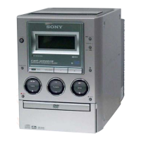
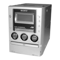
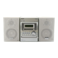
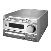
Identifies and describes each control, button, and indicator on the front panel.
Identifies and describes all connectors and terminals located on the rear panel.
Provides step-by-step instructions for setting the unit's clock time.
Details steps for removing the outer case and the front panel assembly.
Outlines the process for disassembling the door assembly and removing the back panel.
Describes the steps for removing the main board and the power transformer.
Details the removal of the sub chassis and the CD mechanism deck.
Explains the steps for disassembling the CD base unit and the BD board/sled motor.
Details the procedure for removing the optical pick-up and the tape mechanism deck.
Provides instructions for disassembling the panel board, including component removal.
Explains how to remove the cassette board and the capstan motor.
Covers MC Cold/Hot Reset, CD Initial, CD Line Test, and CD Memo All Clear procedures.
Explains GC Test Mode, key checks, VACS, and the aging mode entry/exit procedures.
Details AM Tuner step selection, CD SRAM test, and GC VACS ON/OFF modes.
Provides torque specifications and measurement procedures for the tape mechanism.
Explains how to align the disc sensor using an oscilloscope.
Continues the procedure for CD disc sensor alignment, focusing on waveform observation and adjustment.
Details alignment procedures for the magnet assembly and disc holder A.
Outlines test tape usage and procedures for azimuth, tape speed, and playback level adjustments.
Continues tape speed and playback level adjustments for DECK A/B, including sample values.
Covers RF signal checks, E-F balance, and traverse waveform analysis.
Details procedures for S-curve, RF level, and RF PLL free-run frequency checks.
Presents a high-level block diagram of the CD section, showing signal paths and major components.
Illustrates the main section schematic, detailing audio processing, power, and control signal flows.
Provides the schematic diagram for the audio section, including tuner, amplifier, and tape components.
Explains common notes for PWB diagrams and schematic symbols, including signal path indicators.
Shows the printed wiring board layout for the BD section, indicating component placement.
Displays the printed wiring board layout for the CD motor section, including sensor and door switch boards.
Illustrates the printed wiring board layout for the audio section, detailing component placement on the cassette board.
Provides the schematic diagram for the BD section, illustrating circuit connections and component functions.
Presents the schematic diagram for the CD motor section, showing sensor and motor control circuits.
Provides the schematic diagram for the audio section, focusing on the cassette board and leaf switch board circuits.
Shows the first part of the main section schematic, covering RF and FM/AM tuner input stages.
Continues the main section schematic, detailing RF amplifier, PLL, and tuner circuitry.
Presents the second part of the main section schematic, focusing on the master control IC and related circuits.
Illustrates the third part of the main section schematic, covering DSP and mixing amplifier circuits.
Shows the fourth part of the main section schematic, detailing volume controls and various signal processing paths.
Provides the fifth part of the main section schematic, focusing on system control IC and power management.
Presents the final part of the main section schematic, detailing power supply circuits and fan control.
Shows the printed wiring board and schematic diagram for the power section, including transformer and regulator circuits.
Displays the printed wiring board layouts for the panel section, including panel, CD LED, and door LED boards.
Provides the schematic diagram for the panel section, illustrating display control and keypad matrix circuits.
Shows the PWB layouts for the front amplifier and phones boards, detailing component placement.
Provides the schematic diagram for the front amplifier section, including power output stages and protection circuits.
Details the schematic diagram for the rear amplifier section, including surround and center speaker outputs.
Shows the printed wiring board layout for the rear amplifier section, indicating component placement and connections.
Illustrates and describes various waveforms observed during CD section testing, including RF and S-curve signals.
Lists pin functions for key ICs in the CD section, such as LA9240M and LC72136.
Continues the description of IC pin functions, covering more details for LA9240M and related circuits.
Details the pin functions for IC401 (CXP84632-158Q) on the main board, responsible for CD changer control.
Continues the pin function descriptions for IC401 (CXP84632-158Q), covering pins 29 through 64.
Lists the pin functions for IC501 (CXP84632-159Q) on the main board, acting as the master control IC.
Details the pin functions for IC501 (CXP84632-159Q), covering pins 6 through 50.
Continues the pin function descriptions for IC501 (CXP84632-159Q), covering pins 51 through 80.
Lists the pin functions for IC601 (TMP87CM74AF-1G57) on the panel board, responsible for display control.
Shows block diagrams for IC603 (Panel), IC461 (Main), and IC301/IC361 (Cassette) boards.
Provides block diagrams for IC101 (TDA7440D) and IC201 (M62464FP) on the main board.
Shows block diagrams for IC1 (LA1833N) and IC2 (LC72136) on the main board, related to tuner functions.
Illustrates the exploded view of the case section, detailing parts and their assembly order.
Shows the exploded view of the front panel section, listing all components and their part numbers.
Provides the exploded view of the chassis section, detailing internal mechanical parts and transformers.
Illustrates the first part of the mechanism deck exploded view, focusing on the CD mechanism components.
Shows the second part of the mechanism deck exploded view, detailing motors, sensors, and gears.
Provides the exploded view of the optical pick-up section, showing the laser assembly and related parts.
Illustrates the exploded view of the tape mechanism deck, detailing belts, levers, and pinch components.
Lists electrical components for the BD board, including capacitors, connectors, diodes, ICs, and resistors.
Continues the list of electrical components for the BD board, detailing resistors and capacitors.
Lists components for Cassette, CD Door, and CD LED boards, including transistors, resistors, and diodes.
Lists components for CD Motor, Disc Sensor, Door LED, and Front Amp boards, including ICs, transistors, and resistors.
Lists components for Front Amp, SP Term, and Main boards, including resistors, connectors, and capacitors.
Continues the list of electrical components for the Main board, detailing capacitors, connectors, and diodes.
Continues the list of electrical components for the Main board, including capacitors, connectors, and diodes.
Continues the list of electrical components for the Main board, detailing transistors and diodes.
Continues the list of electrical components for the Main board, primarily detailing resistors.
Lists components for Main and Panel boards, including resistors, switches, connectors, and capacitors.
Continues the list of electrical components for the Panel board, including capacitors, diodes, ICs, and transistors.
Lists components for Panel, Phone, and Rear Amp boards, including switches, diodes, and transistors.
Details electrical components for the Rear Amp board, including capacitors, resistors, transistors, and diodes.
Lists components for Rear SP Term, Sub Trans, and Transformer sections, including connectors, diodes, and fuses.
Lists miscellaneous parts such as wires, cords, motors, transformers, and the optical pick-up unit.
Provides a log of revisions made to the service manual, including version number, date, and description.
| Type | Mini Hi-Fi Component System |
|---|---|
| Power Output | 100 W |
| Number of Channels | 2 |
| CD Player | Yes |
| CD Changer | No |
| Tuner | Yes |
| Tuner Bands | FM/AM |
| Cassette Deck | Yes |
| Tape Deck | Yes |
| Bluetooth | No |
| USB Port | No |
| Speakers | 2 |
| Remote Control | Yes |


 Loading...