EasyManua.ls Logo

Sony HCD-MG110 User Manual

Sony HCD-MG110
74 pages
To Next Page IconTo Next Page
Page #1 background imageLoading...
Page #1 background image
SERVICE MANUAL
HC D-MG310AV only
This stereo system is equipped with the Dolby* Pro Logic
Surround decoder.
* Manufactured under license from Dolby Laboratories.
Dolby, Pro Logic, and the double-D symbol ; are
trademarks of Dolby Laboratories. Confidential
unpublished works. '1992-1997 Dolby Laboratories.
All rights reserved.
Amplifier section
U.S.A. models:
AUDIO POWER SPECIFICATIONS
POWER OUTPUT AND TOTAL
HARMONIC DISTORTION:
with 8 ohm loads both channels driven, from
120 – 10,000 Hz; rated 75 watts per channel
minimum RMS power, with no more than 10%
total harmonic distortion from 250 milliwatts to
rated output.
MHC-MG310AV
Front speaker:
Continuous RMS power output
75 + 75 watts
(8 ohms at 1 kHz,
10% THD)
Total harmonic distortion less than 0.09%
(8 ohms at 1 kHz,
40 watts)
Center speaker:
Continuous RMS power output
25 watts
(8 ohms at 1 kHz,
10% THD)
Rear speaker:
Continuous RMS power output
25 + 25 watts
(8 ohms at 1 kHz,
10% THD)
MHC-MG110
Continuous RMS power output
75 + 75 watts
(8 ohms at 1 kHz,
10% THD)
Total harmonic distortion less than 0.09%
(8 ohms at 1 kHz,
40 watts)
Inputs
VIDEO/MD IN (phono jacks):
voltage 250 mV/450 mV,
impedance 47 kilohms
5.1CH (MG310AV only):
FRONT (phono jacks): voltage 450 mV,
impedance 47 kilohms
REAR (phono jacks): voltage 450 mV,
impedance 47 kilohms
CENTER (phono jack): voltage 450 mV,
impedance 47 kilohms
SUB WOOFER (phono jack):
voltage 450 mV,
impedance 47 kilohms
Outputs
PHONES (stereo phone jack):
accepts headphones of
8 ohms or more
FRONT SPEAKER: accepts impedance of 8 to
16 ohms (except for the
US,
SURROUND SPEAKER REAR
(MG310AV only): accepts impedance of 8 to
16 ohms (except for the US,
Cnadian and Mexican model)
SURROUND SPEAKER SUB WOOFER
(MHC-MG510AV only): accepts impedance of
8 ohms (except for the
North American model)
SUB WOOFER (MHC-MG310AV only):
voltage 1 V,
impedance 1 kilohm
CD player section
System Compact disc and digital
audio system
Laser Semiconductor laser
( = 780 nm)
Emission duration:
continuous
Frequency response 2 Hz – 20 kHz (±0.5 dB)
Wavelength 780 – 790 nm
Signal-to-noise ratio More than 90 dB
Dynamic range More than 90 dB
OPTICAL OUT (CD)
(Square optical connector jack, rear panel)
Wavelength 660 nm
Output Level –18 dBm
Tape player section
Recording system 4-track 2-channel stereo
Frequency response 40 – 13,000 Hz (±3 dB),
using Sony TYPE I
cassette
Tuner section
FM stereo, FM/AM superheterodyne tuner
Cnadian and Mexican model)
US Model
Canadian Model
HCD-MG110/MG310AV
Mexican Model
HCD-MG110
Australian Model
HCD-MG310AV
HCD-MG110/MG310AV
Ver 1.3 2002.05
9-873-801-14 Sony Corporation
2002E0500-1 Home Audio Company
C 2002.05 Published by Sony Engineering Corporation
COMPACT DISC DECK RECEIVER
SPECIFICATIONS
HCD-MG110/MG310AV are the Amplifier, CD player, Tape
Deck and Tuner section in MHC-MG110/MG310AV.
– Continued on next page –
Model Name Using Similar Mechanism NEW
CD
CD Mechanism Type CDM64-K1BD44A
Section
Base Unit Name BU-K1BD44A
Optical Pick-up Name KSM-213BFN
TAPE
Model Name Using Similar Mechanism NEW
Section
Tape Transport Mechanism Type CM8L6Z511A
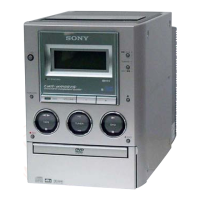
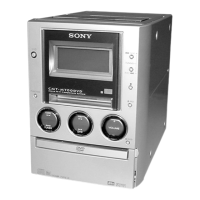
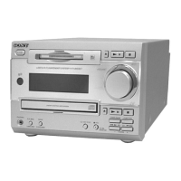
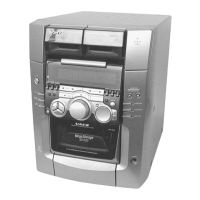
Photo: HCD-MG110

Table of Contents

Question and Answer IconNeed help?

Do you have a question about the Sony HCD-MG110 and is the answer not in the manual?

Sony HCD-MG110 Specifications

General IconGeneral
TypeMini Hi-Fi System
CD PlayerYes
TunerYes
Tuner BandsFM/AM
USB PortYes
Number of Cassette Decks1
Remote ControlYes
Speaker Configuration2.0
ConnectivityHeadphone Out
FunctionsCD, Tuner, Cassette
CD Player TypeSingle Disc

Summary

SPECIFICATIONS

Amplifier section

Details on audio power output and total harmonic distortion for different channels.

CD player section

Specifications for the CD mechanism, laser, frequency response, and signal-to-noise ratio.

Tape player section

Specifications for the tape transport mechanism and frequency response.

Tuner section

Specifications for FM and AM tuning ranges and intermediate frequencies.

SERVICING NOTES

CD-TEXT TEST DISC

Procedure for checking CD-TEXT display functionality using a specialized test disc.

CLEANING OBJECTIVE LENS OF OPTICAL PICK-UP

Instructions on how to safely clean the optical pick-up lens to ensure proper CD playback.

GENERAL

Parts Identification

Identifies and locates various parts and buttons on the main unit of the stereo system.

DISASSEMBLY

DISASSEMBLY FLOW

Outlines the step-by-step sequence for disassembling the entire stereo system.

CD MECHANISM DECK (CDM64-K1BD44A)

Exploded view and steps for removing the CD mechanism deck, critical for CD drive repair.

MECH DECK (TAPE)

Steps for disassembling the tape mechanism deck, critical for tape drive repairs.

TEST MODE

MC Cold Reset

Resets all data and preset data in RAM to initial conditions, useful after repairs.

CD Service Mode

Enables optional CD sled motor operation for tasks like optical pick-up cleaning.

MECHANICAL ADJUSTMENTS

TAPE MECHANISM DECK SECTION

Precautions and procedures for mechanical adjustments related to the tape deck, including torque measurement.

ELECTRICAL ADJUSTMENTS

DECK SECTION

Procedures for electrical adjustments related to the tape deck section.

Record/Playback Head Azimuth Adjustment

Procedure for aligning the record/playback heads for optimal audio quality.

DIAGRAMS

BLOCK DIAGRAM – CD SERVO Section –

Illustrates the signal flow and components within the CD servo control system.

IC PIN FUNCTION DESCRIPTION

Detailed listing of pin functions for key integrated circuits, essential for troubleshooting.

EXPLODED VIEWS

GENERAL SECTION

Provides an overall exploded view of the main unit, identifying major external parts.

MECHANISM DECK SECTION (CDM64-K1BD44A)

Exploded view of the CD mechanism deck, detailing its components and assembly.

ELECTRICAL PARTS LIST

CD BOARD

Comprehensive list of electronic components on the CD board, essential for component replacement.

MAIN BOARD

Detailed list of electronic components used on the main board, essential for component replacement.

Related product manuals