EasyManua.ls Logo

Sony HCD-MC3AV User Manual

Sony HCD-MC3AV
82 pages
To Next Page IconTo Next Page
Page #1 background imageLoading...
Page #1 background image
HCD-MC3AV
US Model
Canadian Model
Australian Model
SERVICE MANUAL
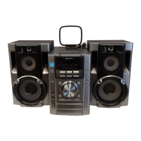
MINI HI-FI COMPONENT SYSTEM
MICROFILM
Manufactured under license from Dolby Laboratories
Licensing Corporation.
“DOLBY” and the double-D symbol a and “PRO
LOGIC” are trademarks of Dolby Laboratories
Licensing Corporation.
HCD-MC3AV is the tuner, deck,
CD and amplifier section in MHC-MC3AV.
— Continued on next page —
SPECIFICATIONS
Model Name Using Similar Mechanism HCD-F150/FR10
CD Mechanism Type CDM-46B1
Optical Pick-up Name KSS-213BA/F-NP
Model Name Using Similar Mechanism HCD-DR8AV
Tape Transport Mechanism Type
TCM-230AWR2/230PWR2
CD
Section
Tape deck
Section
Amplifier section
U.S.A models:
AUDIO POWER SPECIFICATIONS
POWER OUTPUT AND TOTAL HARMONIC DISTORTION:
With 8 loads both channels driven, from 70 – 20,000 Hz; rated 80 W per
channel minimum RMS power, with no more than 0.9% total harmonic
distortion from 250 mW to read output.
North American model:
Front Speaker:
Continuous RMS power output
80 + 80 W
(8 at 1 kHz, 10% THD)
Total harmonic distortion
less than 0.09%
(8 at 1 kHz, 40 W)
Center Speaker:
Continuous RMS power output
20 W
(8 at 1 kHz. 1% THD)
Rear Speaker:
Continuous RMS power output
10 + 10 W
(16 at 1 kHz, 1% THD)
Australian model:
The following measured at AC 240 V, 60 Hz;
Front Speaker:
DIN power output (Rated)
70 + 70 W
(8 at 1 kHz, DIN)
Continuous RMS power output (Reference)
80 + 80 W
(8 at 1 kHz, 10% THD)
Center Speaker:
DIN power output (Rated)
17.5 W
(8 at 1 kHz, DIN)
Continuous RMS power output (Reference)
20 W
(8 at 1 kHz, 10% THD)
Rear Speaker:
DIN power output (Rated)
8 + 8 W
(8 at 1 kHz, DIN)
Continuous RMS power output (Reference)
10 + 10 W
(8 at 1 kHz, 10% THD)
Question and Answer IconNeed help?

Do you have a question about the Sony HCD-MC3AV and is the answer not in the manual?

Sony HCD-MC3AV Specifications

General IconGeneral
BrandSony
ModelHCD-MC3AV
CategoryStereo System
LanguageEnglish

Summary

Specifications

Audio Power Output Specifications

Details on output power and harmonic distortion for different models.

CD, Tuner, and Tape Player Specifications

Technical details for CD mechanism, tuner ranges, and tape player performance.

General Unit and Power Specifications

Power requirements, dimensions, mass, and supplied accessories.

Safety and Servicing Information

Safety Check-Out Procedures

Guidelines for safety checks, including AC leakage testing.

Critical Component Warnings

Important safety notices regarding components vital for safe operation.

Servicing Notes and Handling Precautions

Guidelines for handling optical components and repairing circuit boards.

Unit Overview and Disassembly Steps

Front and Rear Panel Identification

Identification of controls, connectors, and ports on the front and rear panels.

Detailed Component Disassembly

Step-by-step instructions for disassembling the unit's case, panels, boards, and mechanisms.

Section 3 Test Mode

System Test Mode Operations

Procedures for various test modes like MC, CD, GC, Aging, and Function changes.

MC Test Mode and Other Specific Modes

Procedures for MC Test Mode, Aging Mode, and Function Change Modes.

Section 4 Mechanical Adjustments

Tape Mechanism Adjustments

Precautions, torque measurements, and adjustment points for tape mechanism.

CD Mechanism Adjustments

Procedures for adjusting the CD mechanism, including disc sensor alignment.

Section 5 Electrical Adjustments

Deck Section Electrical Adjustments

Adjustments for tape speed, bias, playback level, and record level.

CD Section Electrical Adjustments

Procedures for CD section checks like S Curve, E-F Balance, and RF Level.

Section 6 Diagrams

Block Diagrams and Printed Wiring Boards

High-level block diagrams and component layout diagrams for various sections.

Schematic Diagrams

Detailed circuit schematics for BD, Audio, Main, Panel, Surround, and Power sections.

Waveforms and IC Pin Functions

Oscilloscope waveforms and descriptions of IC pin functions for key components.

Section 7 Exploded Views

Component Assembly Views

Exploded diagrams showing the physical assembly of case, front panel, and chassis.

Mechanism and Optical Unit Views

Exploded views and parts lists for CD mechanisms, optical pick-up, and TC mechanisms.

Section 8 Electrical Parts List

Audio, BD, and Panel Component Lists

Comprehensive parts lists for Audio, BD, CD Door, CD LED, and Panel sections.

Main and Power Amp Component Lists

Parts lists for Main board and Power amplifier board.

Transistor, Coil, and Connector Lists

Detailed lists of transistors, coils, connectors, and other components for Main section.

Miscellaneous Parts Lists

Parts lists for SURR, SW/POWER, TABLE SENSOR, TRANS boards and hardware.

Related product manuals