EasyManua.ls Logo

Sony HCD-M333 User Manual

Sony HCD-M333
112 pages
To Next Page IconTo Next Page
Page #1 background imageLoading...
Page #1 background image
HCD-M333
MICRO HI-FI COMPONENT SYSTEM
SPECIFICATIONS
HCD-M333 is the Amplifier, CD player, MD
deck, Tape player and Tuner section in
CMT-M333NT.
Model Name Using Similar Mechanism NEW
CD Mechanism Type CDM55A-30BBD61B
Base Unit Type BU-30BBD61B
Optical Pick-up Type A-MAX. 3
Model Name Using Similar Mechanism HCD-CP505
MD Mechanism Type MDM-7S2D
Optical Pick-up Type KMS-262E
Model Name Using Similar Mechanism NEW
Tape Transport Mechanism Type CMAL1Z-236A
CD
Section
MD
Section
Tape deck
Section
9-877-180-02
2003E16-1
© 2003.05
Ver 1.1 2003. 05
SERVICE MANUAL
Sony Corporation
Home Audio Company
Published by Sony Engineering Corporation
Amplifier section
European model:
DIN power output (rated): 20 + 20 W
(6 ohms at 1 kHz, DIN)
Continuous RMS power output (reference):
25 + 25 W
(6 ohms at 1 kHz, 10%
THD)
Music power output (reference):
45 + 45 W
Other models:
DIN power output: 20 + 20 W
(6 ohms at 1 kHz, DIN)
Continuous RMS power output (reference):
25 + 25 W
(6 ohms at 1 kHz, 10%
THD)
Inputs
ANALOG IN: Sensitivity 250 mV,
impedance 47 kilohms
DIGITAL OPTICAL IN (supported sampling
frequencies: 32 kHz, 44.1 kHz and 48 kHz)
Outputs
PHONES (stereo minijack):
accepts headphones with
an impedance of 8 ohms or
more
SPEAKER: accepts impedance of 6 to
16 ohms
CD player section
Laser Semiconductor laser
(CD: λ=780 nm)
Emission duration:
continuous
Frequency response 2 Hz – 20 kHz
MD deck section
System Minidisc digital audio
system
Laser Semiconductor laser
(λ=780 nm)
Emission duration:
continuous
Sampling frequency 44.1 kHz
Frequency response 5 Hz – 20 kHz
Tape deck section
Recording system 4-track 2-channel stereo
Frequency response 60 – 10,000 Hz (±3 dB),
using Sony TYPE I
cassettes
Canadian model:
Continuous RMS power output (reference):
25 + 25 W
(6 ohms at 1 kHz, 10%
THD)
Total harmonic distortion less than 0.09%
(6 ohms at 1 kHz, 6 W)
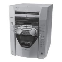
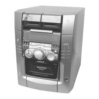
Photo : SILVER TYPE
US and foreign pafents lisensed from Dolby
Labaratories.
— Continued on next page —
Canadian Model
AEP Model
UK Model
E Model
Chinese Model
Australian Model
w
w
w
.
x
i
a
o
y
u
1
6
3
.
c
o
m
Q
Q
3
7
6
3
1
5
1
5
0
9
9
2
8
9
4
2
9
8
T
E
L
1
3
9
4
2
2
9
6
5
1
3
9
9
2
8
9
4
2
9
8
0
5
1
5
1
3
6
7
3
Q
Q
TEL 13942296513 QQ 376315150 892498299
http://www.xiaoyu163.com

Table of Contents

Question and Answer IconNeed help?

Do you have a question about the Sony HCD-M333 and is the answer not in the manual?

Sony HCD-M333 Specifications

General IconGeneral
TypeMini Hi-Fi System
Power Output100 W
CD PlayerYes
TunerFM/AM
BluetoothNo
USB PlaybackNo
Remote ControlYes
SpeakersIncluded
Output Power100 W
Speaker Configuration2.0

Summary

SPECIFICATIONS

CD Section

Details about CD mechanism including model name and type.

MD Section

Details about MD mechanism including model name and type.

Amplifier section

Power output and harmonic distortion specifications for different models.

Tuner section

FM tuner section

Tuning range and aerial specifications for the FM tuner.

AM tuner section

Tuning range and aerial specifications for the AM tuner.

Handling Precautions

Optical Pick-up Handling

Precautions for handling the optical pick-up block.

Laser Diode Emission Check

Safety notes for checking laser diode emission.

SERVICING NOTES

DISASSEMBLY

Top Panel Section

Procedure for removing the top panel.

CD Mechanism Deck (CDM55A-30BBD61B)

Procedure for removing the CD mechanism deck.

TEST MODE

ELECTRICAL ADJUSTMENTS

TAPE SECTION

Electrical adjustments for the tape section.

MD SECTION

Electrical adjustments for the MD section.

Self-diagnosis display

C11/Protected

MD protected against erasure error.

C12/Cannot Copy

Error when copying unsupported CD format.

C13/REC Error

Recording error due to unstable place or dirty disc.

Messages

CD Messages

Messages related to CD operations.

MD Messages

Messages related to MD operations.

Optional Personal Computer Functions

Computer Connectivity

Checks for PC connection and status.

Net MD Operations

Messages related to Net MD functions.

How to Operate Self-diagnosis Function

Error History Display Mode

Procedure to access error history.

Error History Mode Items and Contents

Displayed Error Items

Description of error history displays.

Error History Data Erasure

Procedures for erasing error histories.

Table of Error Codes

SECTION 1 SERVICING NOTE

Disc Tray Lock

Function and procedure for locking the disc tray.

Service Position-1 (Checking TC Section)

Procedure for checking the TC section.

Service Position-2 (Checking CD Mechanism and MD Mechanism Section)

Service Position-3 (Checking Power Supply Section)

Jig For Checking BD (MD) Board Waveform

Terminal Names and Checking Items

List of terminals and their functions.

Iop Data Recording and Display

Record Procedure

Steps to record Iop data.

Display Procedure

Steps to display Iop data.

Laser Power Check Criteria

Criteria for determining laser power adequacy.

SECTION 2 GENERAL

Main unit Controls

Description of the main unit controls.

Button Descriptions

Description of buttons on the main unit.

Remote control

Button Descriptions

Description of remote control buttons.

Alphabetical Order

List of remote controls A-L and M-Z.

SECTION 3 DISASSEMBLY

Top Panel Section

Procedure for removing the top panel.

Front Panel Section

Procedure for removing the front panel.

MAIN Board

Procedure for removing the main board.

3-1. Top Panel Section

3-2. Cassette Mechanism Deck

3-3. Front Panel Section

3-4. PANEL Board, H/P Board, LED Board

3-5. Back Panel Section

3-6. MAIN Board

3-7. MD Mechanism Deck (MDM-7S2D)

3-8. MD DIGITAL Board

3-9. Holder Assy

3-10. BD (MD) Board

3-11. Motor Section

3-12. Over Write Head (HR901)

3-13. Mini Disc Device (KMS-262E)

3-14. POWER Board, Tuner (FM/AM)

3-15. REG Board, AMP Board

3-16. TRANS Board

3-17. CD Mechanism Deck (CDM55A-30BBD61B)

3-18. Cam (CDM55)

3-19. Base Unit (BU-30BBD61B)

3-20. Optical Pick Up (BU-30B Assy)

SECTION 4 TEST MODE

Cold Reset

Procedure for clearing all preset data.

Panel Test Mode

Checks software version, LCD, LED, and keyboard.

Common Test Mode

Mode for testing amplifier and tape functions.

CD Ship Mode (Setting the Position for Transportation)

Ship Mode (Setting the Position for Transportation)

Disc Tray Lock

Repeat 5 Times Limit Release Mode

MD TEST MODE

Precautions For Use of Test Mode

Safety guidelines for MD test mode.

Setting the Test Mode

Procedure to enter MD test mode.

Basic Operations of the Test Mode

Explanation of test mode buttons.

Test Mode Table

AUTO CHECK

Automatic self-diagnosis.

Err Display

Error history display and clear.

Laser power adjustment

Adjustment of laser power.

Operating the Continuous Recording Mode

Functions of Other Buttons

Automatic Self-diagnosis Function

SECTION 5 ELECTRICAL ADJUSTMENTS

TAPE SECTION

Adjustments for tape speed and azimuth.

Record/Playback Head Azimuth Adjustment

Procedure for azimuth adjustment.

Tape Speed Check

Procedure for checking tape speed.

Record Bias Adjustment

Record Level Adjustment

CD SECTION

E-F Balance (1 Track jump) Check

Procedure for checking E-F balance.

RF Level Check

Procedure for checking RF signal level.

MD SECTION

Parts Replacement and Adjustment

Check before replacing parts for MD issues.

Check before replacement

Flowchart for diagnosing MD issues.

Flow Chart for Adjustment

IC195 replacement

Initialisation of non-volatile memory.

OP or IC195 replacement

Initial setting of adjustment value.

Laser power adjustment

Steps for laser power adjustment.

Precautions for Checking Laser Diode Emission

Precautions for Use of Optical Pick-Up (KMS-262A/262E)

Precautions for Adjustments

Checks Prior to Repairs

Temperature Compensation Offset Check

Procedure for checking temperature offset.

Laser Power Check

Procedure for checking laser power.

Iop Compare

Comparing current Iop with reference Iop.

Auto Check

Traverse Check

Focus Bias Check

C Play Check

Self-Recording/playback Check

Initial Setting of Adjustment Value

Recording and Displaying the Iop Information

Temperature Compensation Offset Adjustment

Laser Power Adjustment

Traverse Adjustment

Focus Bias Adjustment

Error Rate Check

CD Error Rate Check

Procedure to check CD error rate.

MO Error Rate Check

Procedure to check MO error rate.

Auto Gain Control Output Level Adjustment

Adjustment and checking Loacation

SECTION 6 DIAGRAMS

Circuit Boards Location

Diagram showing the location of circuit boards.

Waveforms

Diagrams of various waveforms.

6-2. Block Diagrams – CD Section –

– MD Section –

– USB Section –

– MAIN Section –

6-3. Printed Wiring Board – BD (CD) Board –

6-4. Schematic Diagram – BD (CD) Board –

6-5. Printed Wiring Board – BD (MD) Board –

6-6. Schematic Diagram – BD (MD) Board (1/2) –

6-7. Schematic Diagram – BD (MD) Board (2/2) –

6-8. Printed Wiring Board – MD DIGITAL Board –

6-9. Schematic Diagram – MD DIGITAL Board (1/2) –

6-10. Schematic Diagram – MD DIGITAL Board (2/2) –

6-11. Printed Wiring Board – TC Board –

6-12. Schematic Diagram – TC Board –

6-13. Printed Wiring Board – MAIN Section –

6-14. Schematic Diagram – MAIN Section (1/2) –

6-15. Schematic Diagram – MAIN Section (2/2) –

6-16. Printed Wiring Board – H/P Board –

6-17. Schematic Diagram – H/P Board –

6-18. Printed Wiring Board – PANEL Section –

6-19. Schematic Diagram – PANEL Section –

6-20. Printed Wiring Board – REG Board / TRANS Board –

6-21. Schematic Diagram – REG Board / TRANS Board –

6-22. Printed Wiring Board – AMP Board –

6-23. Schematic Diagram – AMP Board –

6-24. Printed Wiring Board – POWER Board –

6-25. Schematic Diagram – POWER Board –

6-26. IC Block Diagrams – BD (CD) Board –

– BD (MD) Board – IC102 AN41050

IC103 CXA2581N-T4

IC104 TC74HC4052AFT(EL)

– BD (MD) Board – IC101 CXA2523AR

IC201 CXD2664R

IC401 BH6519FS-E2

IC803 CY24115-2SCT

IC701 AK4584VQ

IC705 CXD1875TQ

IC706 PCM2903EG/2K

IC721 M62016FP-E1

IC753 TC7WH74FU(TE12R)

IC781 LB1830M-S-TE-L

IC102 LC75342

IC220 BA6956AN

IC Pin Function Description

IC Pin Function Description

IC705 CXD1875TQ

Pin functions for IC705.

SECTION 7 EXPLODED VIEWS

Overall Section

Exploded view of the entire unit.

Front Panel Section

Exploded view of the front panel.

MD Mechanism Deck Section-1 (MDM-7S2D)

Exploded view of MD mechanism part 1.

7-2. Front Panel Section

7-3. Back Panel Section

7-4. MD Mechanism Deck Section-1 (MDM-7S2D)

7-5. MD Mechanism Deck Section-2 (MDM-7S2D)

7-6. CD Mechanism Deck Section-1 (CDM55A-30BBD61B)

7-7. CD Mechanism Deck Section-2 (BU-30BBD61B)

SECTION 8 ELECTRICAL PARTS LIST

< CAPACITOR >

List of capacitors.

< CONNECTOR >

List of connectors.

< DIODE >

List of diodes.

< RESISTOR >

< SWITCH >

< CAPACITOR >

< RESISTOR >

< CAPACITOR >

< CONNECTOR >

< DIODE >

< IC >

< COIL >

< RESISTOR >

< RESISTOR >

< CAPACITOR >

< RESISTOR >

< SWITCH >

< CAPACITOR >

< TRANSISTOR >

< RESISTOR >

< RESISTOR >

< CAPACITOR >

< CAPACITOR >

< TRANSISTOR >

< RESISTOR >

< TRANSFORMER >

REVISION HISTORY

Related product manuals