Do you have a question about the Sony HCD-BX3 and is the answer not in the manual?
Instructions for attaching the panel board, including screw usage and hot melt points.
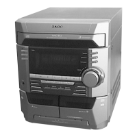
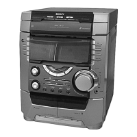
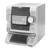
Identifies buttons and indicators on the front panel of the HCD-BX3 unit.
Guide to setting the clock, essential for timer functions, with 12/24 hour system notes.
Instructions for presetting up to 30 FM and 10 AM radio stations.
Steps for removing the upper case (top) of the unit, detailing screw locations.
Instructions for removing the front panel section, including CD mechanism and flat type wires.
Instructions for removing panel, trans, sub-trans, and other board assemblies.
Steps for removing main, amplifier, leaf SW, head, driver, and motor boards.
Instructions for disassembling the base unit and address sensor board.
Covers MC Cold/Hot Reset, CD Ship/Service, and VACS ON/OFF modes.
Procedure for checking operations of Amplifier, Tuner, CD, and Tape sections.
Details aging mode operation, stopping on error, and error display codes.
Covers tape deck sequence during aging and function change modes.
Specifies torque values for FWD, REV, and tension measurements using specific meters.
Details azimuth, speed, and level adjustments using test tapes for the deck section.
Procedures for tape speed, playback level, REC bias, and REC level adjustments.
Covers FM tuned level, CD S-curve, RF level, and E-F balance adjustments.
Procedures for checking RF PLL free-run frequency and RF signal waveform on the BD board.
Diagrams showing circuit board physical locations and example waveforms for key ICs.
Block diagrams illustrating the tuner/CD section and main section circuitry.
Component layouts for BD, MAIN, AMP, PANEL, LEAF SW, DRIVER, and TRANS sections.
Schematic diagrams for BD, MAIN (3 parts), AMP, PANEL, LEAF SW, DRIVER, and TRANS sections.
Detailed pin function description for the MASTER CONTROL IC401 on the main board.
Pin function description for the DISPLAY CONTROL IC601 on the panel board.
Block diagrams for IC101 (CXD2587Q) and IC102 (BA5974FP) on the BD board.
Block diagrams for IC103 (CXA2568M) on BD board and IC701 (BA6956AN) on driver board.
Block diagrams for IC601 (BA1450) and IC651 (LC72130) on the main board.
Exploded view of the main section, listing parts like case, panel, screws, and fan.
Exploded view of the panel section, detailing parts like lids, knobs, brackets, and indicator tube.
Exploded view of the tape mechanism deck, listing parts like pinch levers, heads, belts, and flywheels.
Exploded view of the CD mechanism deck, detailing parts like cams, levers, pulleys, and the optical pick-up block.
List of electrical components for the amplifier section, including capacitors, connectors, and resistors.
Comprehensive list of resistors used in the amplifier and BD sections, with values and ratings.
List of electrical components for the BD driver section, including capacitors, connectors, ICs, transistors, and resistors.
List of electrical components for Head (A/B), Leaf SW, and Main boards, including capacitors and connectors.
Detailed list of capacitors used on the main board, specifying type, value, and voltage.
Further list of main board capacitors, covering various types like ceramic, mylar, and elect.
List of electrical components for the panel section, including diodes, transistors, and transformers.
List of ICs and transistors for the main and trans sections, including part numbers and remarks.
Comprehensive list of resistors used in the panel section, with values, tolerances, and power ratings.
List of panel section resistors R497 through R509, detailing values and tolerances.
List of panel section resistors R523 through R618, detailing values and tolerances.
List of components for main, motor, panel, and trans sections, including transformers, switches, and capacitors.
List of capacitors and diodes for the panel section, specifying types, values, and voltage ratings.
List of resistors and switches for the panel section, including values, tolerances, and types.
List of components for panel, sub-trans, and trans sections, including ICs, transistors, and connectors.
List of components for the trans section, including fuses, resistors, transformers, and hardware.
| Type | Stereo System |
|---|---|
| Speaker Configuration | 2.0 |
| CD Player | Yes |
| Radio Tuner | FM/AM |
| Bluetooth | Yes |
| USB Port | Yes |
| Remote Control | Yes |
| Speakers | Yes |
| Amplifier Output Power | 50W (25W per channel) |
| Inputs | AUX |
| Outputs | Headphone |
| Dimensions (W x H x D) - Speaker | 150 x 240 x 150 mm |