EasyManua.ls Logo

Sony HCD-XG500 - Bookshelf System User Manual

Sony HCD-XG500 - Bookshelf System
80 pages
To Next Page IconTo Next Page
Page #1 background imageLoading...
Page #1 background image
SERVICE MANUAL
COMPACT DISC DECK RECEIVER
US Model
Canadian Model
AEP Model
UK Model
HCD-XG500
E Model
HCD-XG60
SPECIFICATIONS
HCD-XG60/XG500
Photo: HCD-XG60
Ver 1.0 2001.02
9-929-577-11 Sony Corporation
2001B0500-1 Audio Entertainment Group
C 2001.2 General Engineering Dept.
HCD-XG60/XG500 is the amplifier, CD
player, tape deck and tuner section in
LBT-XG60/XG500.
Dolby noise reduction manufactured under license
from Dolby Laboratories Licensing Corporation.
“DOLBY” and the double-D symbol ; are trade-
marks of Dolby Laboratories Licensing Corporation.
Model Name Using Similar Mechanism HCD-LX6/LX50/LX70
CD
CD Mechanism Type CDM37M-5BD32L
Section
Base Unit Name BU-5BD32L
Optical Pick-up Name KSS-213DH
TAPE
Model Name Using Similar Mechanism NEW
Section
Tape Transport Mechanism Type TCM-230PWR42
AUDIO POWER SPECIFICATIONS:
(US model only)
POWER OUTPUT AND TOTAL
HARMONIC DISTORTION
With 6 ohm loads both channels driven, from
120-10,000 Hz; rates 140 watts per channel
minimum RMS power, with no more than 10%
total harmonic distortion.
Amplifier section
Canadian model:
Continuous RMS power output (reference)
160 + 160 watts (6 ohms at
1 kHz, 10% THD)
Total harmonic distortion less than 0.07%
(6 ohms at 1 kHz, 70 W)
AEP, UK models:
DIN power output (rated) 110 + 110 watts
(6 ohms at 1 kHz, DIN)
Continuous RMS power output (reference)
140 + 140 watts
(6 ohms at 1 kHz, 10% THD)
Music power output (reference)
240 + 240 watts
(6 ohms at 1 kHz, 10% THD)
Other models:
The following measured at AC 120/220/240V, 50 Hz
DIN power output (rated) 150 + 150 watts
(6 ohms at 1 kHz, DIN)
Continuous RMS power output (reference)
200 + 200 watts
(6 ohms at 1 kHz, 10% THD)
Inputs
DJ MIX*:
(phono jacks) sensitivity 250 mV,
impedance 47 kilohms
GUITAR IN:
(phone jack) sensitivity 75 mV,
impedance 470 kilohms
PHONO IN:
(phono jacks) sensitivity 3 mV,
impedance 47 kilohms
MIX MIC:
(phone jack) sensitivity 1 mV,
impedance 10 kilohms
VIDEO IN:
(phono jacks) sensitivity 250 mV,
impedance 47 kilohms
GAME IN:
(phono jacks) sensitivity 250 mV,
impedance 47 kilohms
MD IN:
(phono jack) sensitivity 450 mV,
impedance 47 kilohms
Outputs
DJ MIX*:
(phono jacks) sensitivity 250 mV,
impedance 1 kilohms
PHONES:
(stereo phone jack) accepts headphones of 8
ohms or more
VIDEO OUT:
(phono jack) voltage 250 mV
impedance 1 kilohm
MD OUT:
(phono jacks) voltage 250 mV
impedance 1 kilohm
FRONT SPEAKER:
accepts impedance of 6 to
16 ohms
* US, Canadian, AEP, UK, and Mexican models
only
CD player section
System Compact disc and digital
audio system
Laser Semiconductor laser
(λ=780nm), Emission
duration: continuous
Wavelength 780 – 790 nm
Frequency response 2 Hz – 20 kHz (±0.5 dB)
Signal-to-noise ratio More than 90 dB
Dynamic range More than 90 dB
CD OPTICAL DIGITAL OUT
(Square optical connector jack, rear panel)
Wavelength: 660 nm
Output level –18 dBm
– Continued on next page –

Table of Contents

Question and Answer IconNeed help?

Do you have a question about the Sony HCD-XG500 - Bookshelf System and is the answer not in the manual?

Sony HCD-XG500 - Bookshelf System Specifications

General IconGeneral
TypeBookshelf System
BrandSony
ModelHCD-XG500
Power Output100 W
CD PlayerYes
Radio TunerFM/AM
Cassette DeckYes
BluetoothNo
USB PlaybackNo
Remote ControlYes

Summary

Servicing Notes

Handling Optical Pick-up Block

Guidelines for safely handling the optical pick-up block to prevent electrostatic damage.

Laser Diode Emission Check

Procedure for checking laser diode emission, emphasizing safe observation distance.

Disassembly Procedures

Disassembly Flow

Outlines the sequence for disassembling the HCD-XG60/XG500 unit.

Test Modes

MC Cold Reset Mode

Resets the unit to initial conditions, clearing all preset data.

MC Hot Reset Mode

Resets the unit while retaining preset data, similar to power cycling.

CD Delivery Mode

Moves the optical pick-up to a vibration-resistant position for shipping.

Aging Mode

Mode for checking tape deck section operation in parallel.

Mechanical Adjustments

Torque Measurement Specifications

Specifies torque meter readings for various mechanical adjustments.

Electrical Adjustments

Record/Playback Head Azimuth Adjustment

Procedure for adjusting the azimuth of record/playback heads.

Tape Speed Adjustment

Instructions for adjusting tape speed for Deck B.

Playback Level Adjustment

Procedure for adjusting playback signal levels for Deck A and B.

REC Bias Adjustment

Steps for adjusting the recording bias for Deck B.

REC Level Adjustment

Procedure for adjusting the recording level for Deck B.

Diagrams and Waveforms

S-Curve Check

Procedure for checking the S-curve waveform for symmetrical output.

E-F Balance (1 Track Jump) Check

Procedure to check E-F balance and DC voltage on a 1 track jump waveform.

RF Level Check

Procedure for checking the RF signal level waveform.

Block Diagrams

CD Servo Section Block Diagram

Illustrates the signal flow and components of the CD servo system.

Tuner/Tape Deck Section Block Diagram

Shows the block connections for the tuner and tape deck sections.

Main Section Block Diagram

Depicts the overall block diagram for the main processing unit.

Display/Key Control/Power Supply Block Diagram

Illustrates the connections for display, key control, and power supply.

Printed Wiring Boards and Schematic Diagrams

BD Board Schematic

Schematic diagram detailing the BD board circuitry.

CD Motor Section Schematic

Schematic detailing the circuitry for the CD motor section.
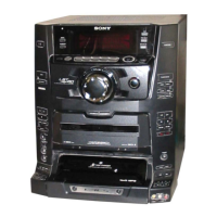
Related product manuals