Do you have a question about the Sony HCD-XGR90AV and is the answer not in the manual?
Procedure to clear all preset data in RAM, returning the set to initial conditions.
Moves the optical pick-up to a position durable to vibration for customer return after repair.
Test mode to check all LEDs and the fluorescent indicator tube, including key function checks.
Mode to run the CD sled motor freely, useful for pick-up cleaning.
Mode for checking the tape deck section operation in parallel.
Sequence of operations during tape deck aging mode, with error handling.
Sequence of operations during CD section aging mode, with error handling.
Specifications for torque measurement of FWD, FWD back tension, and FF/REW modes.
Reference level for deck section adjustments, set to 0 dB = 0.775 V.
Precautions for demagnetizing, tool usage, and performing adjustments with rated power.
Procedure for adjusting the record/playback head azimuth for both decks.
Procedure to adjust tape speed for Deck B using a frequency counter.
Procedure for adjusting REC bias for Deck B, including record level settings.
Procedure for adjusting REC level for Deck B, ensuring proper playback output.
Notes on CD block adjustment, including checks for signal level and waveforms.
Procedure to confirm the S-curve waveform is symmetrical and the peak-to-peak level is within specification.
Procedure to check E-F balance by measuring specific points on the waveform.
Procedure to confirm the RF signal level is clear and correct.
Diagram showing the physical location of various circuit boards within the unit.
Block diagram illustrating the CD servo system components and their interconnections.
Schematic diagram for the tuner and tape deck sections, showing component interconnections.
Schematic diagram of the main processing and control sections of the unit.
Detailed pin functions for IC101 (DIGITAL SIGNAL PROCESSOR) on the BD Board.
Block diagrams for IC101 (CXD3017Q) and IC102 (BA5974FM-E2) on the BD Board.
| Tuner Bands | AM/FM |
|---|---|
| Audio Channels | 2.0 |
| CD Player | Yes |
| Tuner | Yes |
| Cassette Deck | Yes |
| Remote Control | Yes |
| Functions | Cassette |
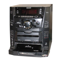
| CD Changer | 3-Disc Changer |
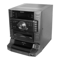
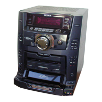
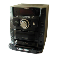
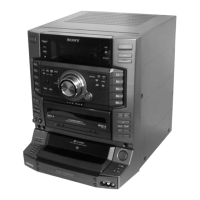
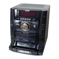
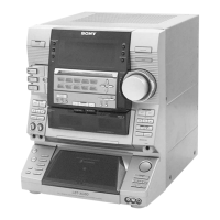
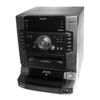
| Type | Mini Hi-Fi Component System |