Do you have a question about the Sony HCD-XGV80 and is the answer not in the manual?
Details about amplifier output and input specifications for different models.
Details about the CD player system, laser, frequency response, and SNR.
Technical details of the tape deck, including recording system and frequency response.
Specifications for FM and AM tuner sections, including tuning range and intermediate frequency.
Procedure for disassembling the main unit's case, identifying screws and components.
Steps for removing and disassembling the front panel section and its connectors.
Instructions for removing the back panel, DC fan, and main board.
Procedure for removing the CD mechanism deck.
LED/Indicator test, Sled Servo, Aging, and Color System changeover modes.
Lists torque values for FWD, FWD back tension, and FF/REW modes.
Sets the deck section to test mode for adjustments, specifying test tapes and signals.
Procedure for adjusting head azimuth for both decks to match output peaks.
Procedure for adjusting tape speed to meet frequency counter requirements.
Checks the symmetry and peak-to-peak level of the S-curve waveform.
Confirms the level B and A on the oscilloscope waveform for 1-track jump.
Checks the clarity and level of the RF signal waveform.
Ensures the video level is 1.0 ± 0.1 Vp-p, satisfying the NTSC standard.
Diagrams showing the physical location of various circuit boards within the unit.
Block diagrams illustrating functional sections like CD Servo and Tuner/Tape Deck.
Schematic diagram for the BD section, detailing circuit connections.
Schematic diagram for the VIDEO section.
Schematic diagram for CD-L and CD-R sections.
Schematic diagram for TC-A and TC-B sections.
Schematic diagram for Panel VR and Key sections.
Detailed pin functions for IC505 (CXD1887R) on the VIDEO board.
Exploded view of the CD mechanism deck, detailing its components.
| Brand | Sony |
|---|---|
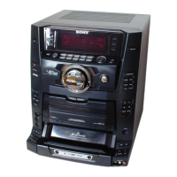
| Model | HCD-XGV80 |
| Category | Stereo System |
| Language | English |