Do you have a question about the Sony HCD-XGR66 and is the answer not in the manual?
Details output power and harmonic distortion for the amplifier section.
Lists specifications for the CD playback mechanism, including laser type and frequency response.
Outlines procedures for checking AC leakage from exposed metal parts to earth ground.
Clears preset data and returns the set to initial conditions, useful for customer returns.
Moves the optical pick-up to a position durable to vibration for shipping.
Activates all LEDs and the indicator tube, and checks key operation.
Allows free movement of the CD sled motor for maintenance tasks.
Tests tape deck and CD section operations in parallel for extended periods.
Lists torque specifications for various mechanical adjustments like FWD and FF/REW.
Specifies test mode entry and settings for tape deck electrical adjustments.
Details the procedure for adjusting the head azimuth for optimal playback and recording.
Illustrates the physical placement of various circuit boards within the unit.
Presents block diagrams of major sections: CD Servo, Tuner/Tape Deck, Main, and Power Supply.
Shows component layout and schematic for the BD board.
Details pin functions for key integrated circuits on the BD and Main boards.
Provides block diagrams for key ICs like CXD3017Q, BA5974FM-E2, and TA8409.
| Cassette Deck | Yes |
|---|---|
| CD Player | Yes |
| Tuner | Yes |
| Outputs | Headphone Jack |
| Remote Control | Yes |
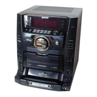
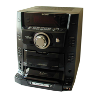
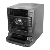
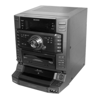
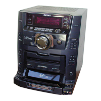
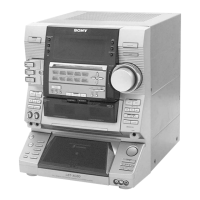
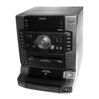
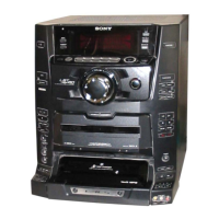
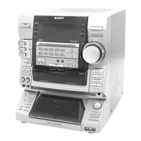
| Type | Mini Stereo System |
| Functions | CD Player, Tuner, Cassette |
| Tuner Bands | FM, AM |
| Inputs | Audio Line-in |