Do you have a question about the Sony HCD-XGR60 and is the answer not in the manual?
Details power output and harmonic distortion for North American and other models.
Lists CD mechanism type, pick-up name, and tape mechanism model.
Details system, laser, frequency response, S/N, tuner ranges, and IF.
Covers power requirements, consumption, dimensions, mass, and supplied accessories.
Provides warnings for component replacement and circuit board repair.
Details methods for checking AC leakage current and safety limits.
Precautions for handling optical pick-ups and laser diodes, including emission checks.
Identifies models and warns about critical safety components.
Alphabetical listing of main unit controls and their corresponding page references.
Instructions for removing the main case and front panel assembly.
Steps for removing the tape mechanism deck and CD mechanism deck.
Procedures for disassembling various boards like Panel FL, VR, MIC/Guitar, Headphone, CD-L/R.
Steps for removing back panel, fan, main board, BD board, and disc table.
Procedures for disassembling Base Units 1 & 2 and related parts.
Procedures for cold reset, AM tuning interval change, and CD ship mode.
Covers LED/Key check, Sled Servo, Function Name change, and Aging Mode.
Details step-by-step sequences for tape deck and CD section aging modes.
Explains how to enable or disable the Volume control by VACS feature.
Precautions for mechanical adjustments and torque specifications.
Precautions for electrical adjustments and required test tapes.
Procedures for adjusting head azimuth and tape speed.
Procedures for adjusting record bias and record level.
Procedures for checking S-curve and E-F balance for proper CD operation.
Steps to check RF signal level and waveform for CD playback.
Illustrates the physical layout and names of various circuit boards.
Shows functional blocks and signal flow in the CD servo system.
Illustrates signal paths for tuner and tape deck sections.
Details signal flow in the main audio processing section.
Shows functional blocks for display, key inputs, and power supply.
Component layout and circuit schematic for the BD board.
Component layout and circuit schematic for motor and LED sections.
Circuit schematic and component layout for the MIC/Guitar input section.
Circuit schematics for the main board (Parts 1, 2, 3).
Component layouts and circuit schematics for CD-related boards.
Component layout and circuit schematic for the Panel VR board.
Component layouts and circuit schematics for Panel FL, TC-A, TC-B boards.
Component layout and circuit schematic for the PA board.
Component layouts and circuit schematics for transformer sections (MX and E,E51,AR models).
Details pin assignments for IC101, the digital signal processor.
Details pin assignments for IC501, the system controller.
Details pin assignments for IC601, the display controller.
Block diagrams for IC101 (DSP) and IC102 (Motor Driver).
Block diagrams for IC103 (RF Amp) and IC321 (Comparator).
Block diagrams for IC201 (Motor Driver) and IC602 (Filter/Detector).
Exploded view and parts list for the case and back panel.
Exploded views and parts lists for the front panel sections.
Exploded views and parts lists for the chassis and CD mechanism deck.
Exploded view and parts list for the base unit section.
Lists components for the BD board (capacitors, ICs, resistors, etc.).
Lists components for the main board (capacitors, ICs, resistors, etc.).
Lists components for Front Input, Headphone, LED, and Main boards.
Lists main board components (connectors, diodes, fuses, resistors).
Continues listing main board components (ICs, jacks, coils, transistors).
Lists main board resistors (R111-R340).
Lists main board resistors (R341-R700).
Lists parts for MIC/Guitar, Motor, and PA boards.
Lists parts for PA and Panel FL boards.
Lists parts for Panel FL and Panel VR boards.
Lists components for Panel VR, Sensor, Sub Trans, TC-A, TC-B, and Trans boards.
Lists components for the Trans board.
Records revisions made to the service manual with version and date.
| Brand | Sony |
|---|---|
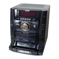
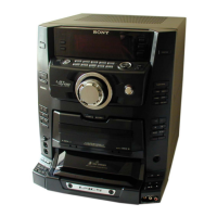
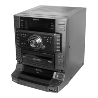
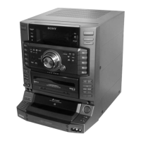
| Model | HCD-XGR60 |
| Category | Stereo System |
| Language | English |