19
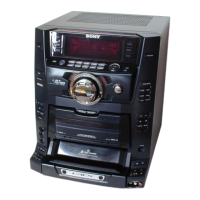
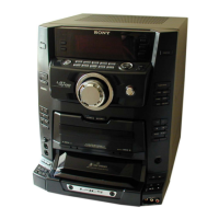
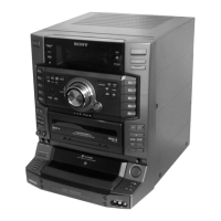
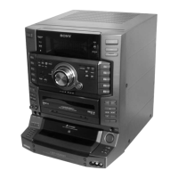
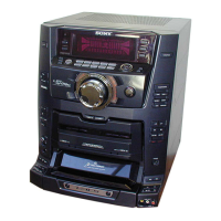
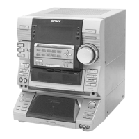
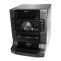
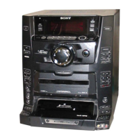
HCD-XGR66/XGR600
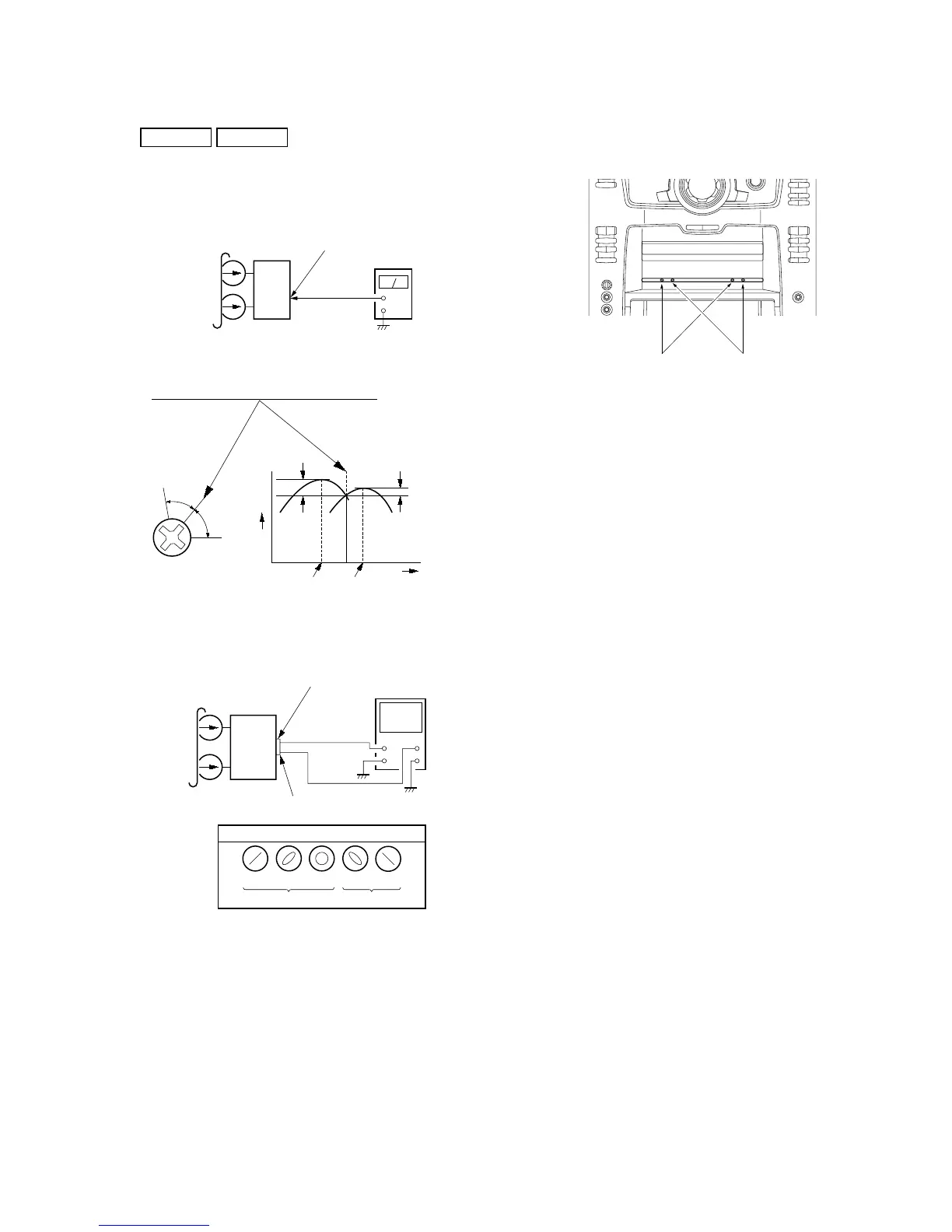
Record/Playback Head Azimuth Adjustment
DECK A DECK B
Note: Perform this adjustments for both decks
Procedure:
1. Mode: Playback (FWD)
set
MAIN board
MD (VIDEO) OUT jack (J701
L-CH, R-CH
+
level meter
test tape
P-4-A100
(10 kHz, – 10 dB)
Screw
position
L-CH
peak
within
1dB
Output
level
L-CH
peak
R-CH
peak
within
1dB
Screw
position
R-CH
peak
3. Mode: Playback
set
test tape
P-4-A100
(10 kHz, – 10 dB)
R-CH
oscilloscope
L-CH
R-CH
V
H
waveform of oscilloscope
in phase 45
°
90
°
135
°
180
°
good
wrong
MAIN board
MD (VIDEO) OUT jack (J701)
L-CH
4. Repeat step 1 to 3 in playback (REV) mode.
5. After the adjustments, apply suitable locking compound to the
pats adjusted.
Adjustment Location: Playback Head (Deck A).
Record/Playback/Erase Head (Deck B).
forward
reverse
2. Turn the adjustment screw and check output peaks. If the peaks
do not match for L-CH and R-CH, turn the adjustment screw
so that outputs match within 1dB of peak.
 Loading...