16
HCD-XG60/XG500
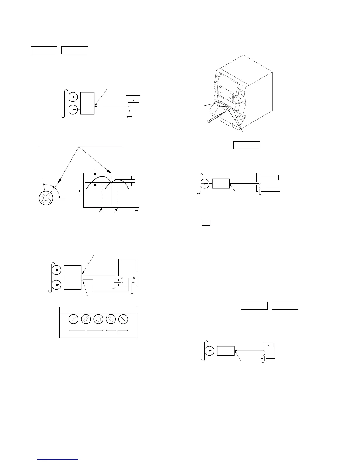
Tape Speed Adjustment DECK B
Mode: Playback
1. Insert the WS-48B into the deck B.
2. Press the H button on the deck B.
3. Press the [H SPEED DUB] button in playback mode.
Then at HIGH speed mode.
4. Adjust RV1001 on the LEAF SW board do that frequency
counter reads 6,000 ± 180 Hz.
5. Press the [H SPEED DUB] button.
Then back to NORMAL speed mode.
6. Adjust RV1002 on the LEAF SW board so that frequency
counter reads 3,000 ± 90 Hz.
Adjustment Location: LEAF SW board
Sample value of Wow and Flutter: 0.3% or less W.RMS (JIS)
(WS-48B)
Playback Level Adjustment DECK A DECK B
Procedure:
Mode: Playback
Deck A is RV311 (L-CH), Deck B is RV301 (L-CH) so that ad-
justment within specification values as follows.
Specification Values:
J101 PB level: 301.5 to 338.3 mV (– 8.2 to – 7.2 dB) level
difference between the channels: within ± 0.5 dB
Adjustment Location: AUDIO board
2. Turn the adjustment screw and check output peaks. If the peaks
do not match for L-CH and R-CH, turn the adjustment screw
so that outputs match within 1dB of peak.
3. Mode: Playback
4. Repeat step 1 to 3 in playback (REV) mode.
5. After the adjustments, apply suitable locking compound to the
pats adjusted.
Screw
position
L-CH
peak
within
1dB
Output
level
L-CH
peak
R-CH
peak
within
1dB
Screw
position
R-CH
peak
set
test tape
P-4-A100
(10 kHz, – 10 dB)
R-CH
oscilloscope
L-CH
R-CH
V
H
waveform of oscilloscope
in phase 45° 90° 135° 180°
good
wrong
MAIN board
MD OUT jack (J701)
L-CH
+
–
set
test tape
WS-48B
(3 kHz, 0 dB)
MAIN board
MD OUT jack (J701)
L-CH, R-CH
frequency counter
+
–
set
test tape
P-4-L300
(315 Hz, 0 dB)
MAIN board
MD OUT jack (J701)
L-CH
level mete

 Loading...