3
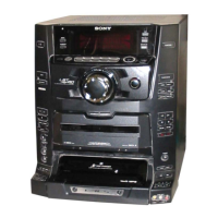
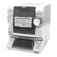
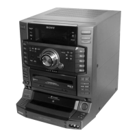
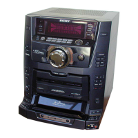
HCD-XG60/XG500
TABLE OF CONTENTS
1. SERVICING NOTES ................................................ 5
2. GENERAL
Location of Controls ....................................................... 6
Setting the Time .............................................................. 7
3. DISASSEMBLY
3-1. Disassembly Flow ........................................................... 8
3-2. Case ................................................................................. 8
3-3. Front Panel Section ......................................................... 9
3-4. Cover (TC), Tape Mechanism Deck
(TCM-230PWR42) ......................................................... 9
3-5. MAIN Board, Fan, D.C. (M901)
(Except AEP, UK Models) .............................................. 10
3-6. MAIN Board (AEP, UK Models) ................................... 10
3-7. CD Mechanism Deck (CDM37M-5BD32L).................. 11
3-8. Base Unit (BU-5B32L) ................................................... 12
3-9. Disc Table ........................................................................ 12
4. TEST MODE.............................................................. 13
5. MECHANICAL ADJUSTMENTS ....................... 15
6. ELECTRICAL ADJUSTMENTS
Deck section .................................................................... 15
CD Section ...................................................................... 18
7. DIAGRAMS
7-1. Block Diagram – CD SERVO Section – ....................... 19
7-2. Block Diagram – TUNER/TAPE DECK Section – ...... 20
7-3. Block Diagram – MAIN Section – ................................ 21
7-4. Block Diagram – DISPLAY/KEY CONTROL/
POWER SUPPLY Section – ........................................... 22
7-5. Note for Printed Wiring Boards and
Schematic Diagrams ....................................................... 23
7-6. Printed Wiring Board – BD Board – ............................. 24
7-7. Schematic Diagram – BD Board – ................................ 25
7-8. Printed Wiring Boards – CD MOTOR Section – .......... 26
7-9. Schematic Diagram – CD MOTOR Section – .............. 27
7-10. Printed Wiring Board – AUDIO Board – ...................... 28
7-11. Schematic Diagram – AUDIO Board – ......................... 29
7-12. Printed Wiring Board – LEAF SW Board – .................. 30
7-13. Schematic Diagram – LEAF SW Board –..................... 30
7-14. Schematic Diagram – MAIN Board (1/3) – .................. 31
7-15. Schematic Diagram – MAIN Board (2/3) – .................. 32
7-16. Schematic Diagram – MAIN Board (3/3) – .................. 33
7-17. Printed Wiring Board – MAIN Board – ........................ 34
7-18. Printed Wiring Board – PA Board – .............................. 36
7-19. Schematic Diagram – PA Board – ................................. 37
7-20. Printed Wiring Boards – MIC/FRONT INPUT/
HEADPHONES Boards –............................................... 38
7-21. Schematic Diagram – MIC/FRONT INPUT/
HEADPHONES Boards – ............................................. 39
7-22. Printed Wiring Board – PANEL FL Board – ................ 40
7-23. Schematic Diagram – PANEL FL Board – ................... 41
7-24. Printed Wiring Boards
– PANEL VR/ILLUMINATION Boards – ..................... 42
7-25. Schematic Diagram
– PANEL VR/ILLUMINATION Boards – ..................... 43
7-26. Printed Wiring Boards – TC-A/TC-B/CD-L/
CD-R (1)/CD-R (2) Boards – ......................................... 44
7-27. Schematic Diagram – TC-A/TC-B/CD-L/
CD-R (1)/CD-R (2) Boards – ......................................... 45
7-28. Printed Wiring Board – TRANSFORMER Section– .... 46
7-29. Schematic Diagram – TRANSFORMER Section–....... 46
7-30. IC Pin Function Description ........................................... 50
8. EXPLODED VIEWS
8-1. Case, Back Panel Section................................................ 55
8-2. Front Panel Section-1...................................................... 56
8-3. Front Panel Section-2...................................................... 57
8-4. Chassis Section ............................................................... 58
8-5. Tape Mechanism Deck Section-1
(TCM-230PWR42) ......................................................... 59
8-6. Tape Mechanism Deck Section-2
(TCM230PWR42)........................................................... 60
8-7. CD Mechanism Deck Section (CDM37M-5BD32L) .... 61
8-8. Base Unit Section (BU-5BD32L) ................................... 62
9. ELECTRICAL PARTS LIST ............................... 63

 Loading...