Do you have a question about the Sony HCD-ED1 and is the answer not in the manual?
Specifications related to the CD playback functionality.
Specifications for the cassette tape playback system.
Technical details for FM and AM radio tuning.
Procedures for safety checks and warnings for safe operation.
Identifies different AC power supply codes for various models.
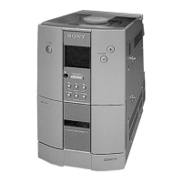
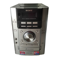
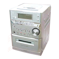
Identifies and locates all front and rear panel controls and connectors.
Step-by-step instructions for setting the system's internal clock.
Instructions for disassembling the CD mechanism and base unit.
Steps to remove the bottom cover and front panel assembly.
Disassembly of the cassette deck and its cover.
Specifications and methods for measuring torque in the tape deck.
Procedure to adjust the tape speed for optimal performance.
Steps to adjust the playback audio signal level.
Procedure for adjusting the bias level during tape recording.
Steps to adjust the recording audio signal level.
How to adjust the focus bias for the optical pick-up.
Checking the E-F balance using a 1 track jump method.
Adjustment of focus and tracking gain, often with a margin.
Illustrates the physical placement of all circuit boards within the unit.
Detailed pinout and function description for the TC9613 master control IC.
Electrical schematic for the CD player circuitry.
Layout of the printed wiring board for the CD section.
Electrical schematic for the system's input and output circuits.
Layout of the printed wiring board for input/output functions.
Layout of the printed wiring board for the tape deck mechanism.
Electrical schematic for the tape deck control and audio circuits.
Electrical schematic for the front panel display and controls.
Layout of the printed wiring board for the display and control sections.
Electrical schematic for the power supply and amplifier circuits.
Layout of the printed wiring board for the power supply section.
Block diagrams illustrating the internal functions of key integrated circuits.
Exploded diagram showing parts of the CD mechanism.
Exploded diagram of the rear panel components and their assembly.
Exploded diagram of the front panel components and their assembly.
Exploded diagram of the cassette mechanism deck.
Exploded diagram of the base unit, including the optical pick-up.
Table indicating changes to parts across different revisions or models.
| Tuner Bands | FM/AM |
|---|---|
| CD Player | Yes |
| Tuner | Yes |
| Type | Mini Hi-Fi System |
| Functions | CD |
| CD Player Type | Single Disc |
| Audio Output | Stereo |
| Speakers | 2 |