Do you have a question about the Sony HCD-EX770 and is the answer not in the manual?
List of included accessories and packing materials for the unit.
General operational parameters and power requirements for the unit.
List of abbreviations used throughout the service manual.
Identification details and labels located on the back panel of the unit.
Instructions for using the karaoke function and microphone.
Details on adjusting sound parameters like bass and treble.
Procedure for disassembling the front panel assembly.
Detailed pin functions for ICs on the panel board.
Exploded view of the chassis and its components.
Exploded view of the front panel and its parts.
Identification details and labels located on the back panel.
Instructions for operating the unit with external service equipment.
Procedure to enter and use the check mode for indicators.
Steps for tuning into radio stations using preset or manual methods.
Guide for naming and storing radio presets with up to eight characters.
Instructions on how to access and display RDS information.
Detailed steps for disassembling the front panel section of the unit.
General precautions to take before performing repairs on the unit.
Procedures for adjusting the AM tuning level.
Procedures for adjusting the FM tuning level.
Detailed pin functions for ICs on the main board.
Waveform examples from the MD mechanism deck section.
Waveform examples from the main/panel/motor section.
IC block diagram for the MD mechanism deck.
Exploded view illustrating the chassis and main mechanical parts.
Exploded view detailing the front panel assembly and its components.
Guidance on providing power to the unit during servicing operations.
Steps to activate and use the check mode for display and buttons.
Method to select input signals by pressing buttons while turning the selector.
General instructions for operating the unit's basic functions.
Instructions for playing audio CDs, including track selection.
Step-by-step guide for recording audio from a CD to a tape deck.
Procedure to halt the recording process.
Information specific to the CD player component.
How to interpret information displayed on the CD player's screen.
Instructions for setting the repeat playback mode for CDs.
Specific instructions for setting the repeat playback function.
How to enable shuffle play for random track playback.
Instructions for activating the shuffle play feature.
Guide to programming a sequence of tracks for playback.
Steps for programming a specific track sequence.
How to create and manage audio loops for parts of a CD.
Instructions for using the loop function.
Explanation of the two looping modes: Normal and Rhythm.
Detailed steps for disassembling the main chassis of the unit.
Procedure for removing and reassembling the CD loading panel.
Steps for disassembling the front panel section of the unit.
Disassembly instructions for the main board and CD mechanism.
Procedure for disassembling the base unit of the CD player.
Steps for disassembling the CD tray mechanism.
Disassembly of the BD board.
Steps for removing the optical pick-up and sled motor assembly.
Crucial safety advice to prevent eye damage when checking laser output.
Handling precautions for the optical pick-up to prevent static damage.
Method for preparing a MO disc for bias and error rate testing.
Procedure for adjusting the focus bias when the optical pick-up is replaced.
Visual reference for the correct RF signal waveform during adjustment.
Procedure to perform an S-curve check for proper operation.
Adjustment procedure for the traverse waveform, ensuring symmetry.
Note regarding focus/tracking gain adjustment, stating it has a margin.
Method for adjusting focus bias based on C1 error rate.
Procedure for checking CD and MO error rates.
How to check focus bias and its tolerance.
Diagram showing the physical placement of various circuit boards.
First part of the block diagram illustrating system signal flow.
Second part of the block diagram showing system signal flow.
Printed wiring board layout for the MD mechanism deck.
Schematic diagram for the MD mechanism deck section.
Schematic diagram for the main and display sections.
Printed wiring board layout for the main and display sections.
Illustrations of various waveforms encountered in the system.
Waveform examples from the MD mechanism deck.
Waveform examples from the main/display section.
Block diagrams illustrating the internal structure of integrated circuits.
IC block diagram for the MD mechanism deck.
Detailed pin functions for integrated circuits.
Pin functions for IC101 on the BD board, an RF amplifier.
Pin functions for IC121 on the BD board, detailing its multiple roles.
Pin functions for IC401, the system controller on the main board.
Exploded view illustrating the chassis and main mechanical parts.
Exploded view of the first part of the MD mechanism deck.
Exploded view of the second part of the MD mechanism deck.
Guidance on providing power to the unit during servicing operations.
Steps to activate and use the check mode for display and buttons.
Method to select input signals by pressing buttons while turning the selector.
General instructions for operating the unit's basic functions.
How to play MD tracks in a random sequence.
Instructions for setting repeat playback for MD tracks.
How to check remaining track time using the MD display.
Guidance on interpreting information shown on the MD display.
Guide to programming a sequence of tracks for MD playback.
Steps for programming a specific track sequence.
Step-by-step guide for recording music onto an MD manually.
Steps to adjust the recording level on the MD deck.
Instructions for recording selected CD tracks onto an MD.
How to select tracks from a CD for recording onto an MD.
Instructions for starting the recording process from CDs.
Instructions for recording from multiple CDs consecutively.
Method to record only the first track from a CD.
Information on starting recordings of prestored audio data.
How to mark track numbers during the recording process.
Function to automatically cut tracks during recording.
Process for automatically marking tracks during recording.
Instructions and procedures for erasing recorded content.
Overview of the erasing function for MD recordings.
Steps to erase a single track from an MD.
How to move recorded tracks on an MD.
How to use the function to move tracks on an MD.
Procedure to erase only a part of a track on an MD.
Steps to erase all tracks from an MD.
How to divide recorded tracks on an MD.
Instructions for dividing recorded tracks.
How to combine recorded tracks on an MD.
Instructions for combining recorded tracks.
Functionality for undoing the last edit operation on an MD.
Functionality for undoing the last edit operation on an MD.
Steps to cancel the track titling process.
How to view existing track titles on the MD.
Procedure to edit or change the title of a track.
Detailed steps for disassembling the front panel section.
Disassembly of the MD mechanism deck.
Exploded view and part list for the mechanism brackets.
Disassembly of the BD board.
Steps for removing and reassembling the sub chassis.
Disassembly of the shutter assembly.
Procedure for removing the overwrite head.
Steps for disassembling the slider complete assembly.
Important notes and guidance for the installation process.
Safety guidelines and precautions before using the test mode.
Explanation of modes related to laser emission and button operations.
Steps to enter the test mode by pressing buttons and connecting power.
Procedure to exit the test mode and return to normal operation.
Overview of buttons and knob functions used within the test mode.
How to select among the thirteen available test modes using the selector knob.
Instructions for using the continuous playback mode.
Guide on how to operate the continuous recording mode.
Information on the EEP mode for reading/writing non-volatile memory.
Description of functions for various buttons not covered elsewhere.
How the display changes in test mode when the button is pressed.
Explanation of various displays shown during test modes.
Crucial safety advice to prevent eye damage when checking laser output.
Handling precautions for the optical pick-up to prevent static damage.
Method for preparing a MO disc for bias and error rate testing.
Procedure for adjusting temperature compensation offset.
Steps to adjust the laser power output to specified levels.
Procedure for adjusting the traverse waveform balance.
Note regarding focus/tracking gain adjustment, stating it has a margin.
Method for adjusting focus bias based on C1 error rate.
Procedure for checking CD and MO error rates.
How to check focus bias and its tolerance.
Identification of adjustment points and connection points on the BD board.
Diagram showing the physical placement of various circuit boards.
First part of the block diagram illustrating system signal flow.
Second part of the block diagram showing system signal flow.
Printed wiring board layout for the MD mechanism deck.
Schematic diagram for the MD mechanism deck section.
Schematic diagram for the main and display sections.
Printed wiring board layout for the main and display sections.
Illustrations of various waveforms encountered in the system.
Waveform examples from the MD mechanism deck.
Waveform examples from the main/display section.
Block diagrams illustrating the internal structure of integrated circuits.
IC block diagram for the MD mechanism deck.
Detailed pin functions for integrated circuits.
Pin functions for IC101 on the BD board, an RF amplifier.
Pin functions for IC121 on the BD board, detailing its multiple roles.
Pin functions for IC401, the system controller on the main board.
Exploded view illustrating the chassis and main mechanical parts.
Exploded view of the first part of the MD mechanism deck.
Exploded view of the second part of the MD mechanism deck.
| Brand | Sony |
|---|---|
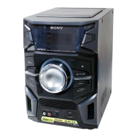
| Model | HCD-EX770 |
| Category | Stereo System |
| Language | English |