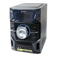
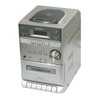
HCD-EX5
US Model
Canadian Model
AEP Model
UK Model
E Model
Australian Model
Chinese Model
SERVICE MANUAL
MICRO Hi-Fi COMPONENT SYSTEM
Sony Corporation
Personal Audio Division
Published by Sony Techno Create Corporation
9-874-036-03
2007B16-1
© 2007.02
Ver. 1.2 2007. 02
SPECIFICATIONS
This set is the tuner, CD and amplifier
section in CMT-EX5
Model Name Using Similar Mechanism NEW
CD Mechanism Type CDM71C-31BD63A
Base Unit Type BU-31BD63A
CD
SECTION
— Continued on next page —
Amplifier section
For the U.S. model
AUDIO POWER SPECIFICATIONS
POWER OUTPUT AND TOTAL
HARMONIC DISTORTION:
With 4 ohms loads, both channels driven, from
120 - 10,000 Hz; rated 12 watts per channel
minimum RMS power, with no more than 10%
total harmonic distortion from 250 milli watts
to rated output.
North American model:
Continuous RMS power output (Reference):
15 + 15 W
(4 ohms at 1 kHz, 10%
THD)
European model:
DIN power output (Rated):12 + 12 W
(4 ohms at 1 kHz, DIN)
Continuous RMS power output (Reference):
15 + 15 W
(4 ohms at 1 kHz, 10%
THD)
Music power output (Reference):
15 + 15 W
Other models:
The following measured at 220 V AC, 60 Hz
DIN power output (Rated):
12 + 12 W
(4 ohms at 1 kHz, DIN,
110 V – 240 V AC)
Continuous RMS power output (Reference):
15 + 15 W
(4 ohms at 1 kHz, 10%
THD, 110 V – 240 V AC)
Inputs
PC/TAPE/MD IN (stereo mini jack):
voltage 450 mV (MD)/
250 mV (PC/TAPE),
impedance 47 kilohms
AM tuner section
Tuning range
Pan-American model: 530 – 1,710 kHz
(with the interval set at
10 kHz)
531 – 1,710 kHz
(with the interval set at
9 kHz)
European model: 531 – 1,602 kHz
(with the interval set at
9 kHz)
Other models: 530 – 1,710 kHz
(with the interval set at
10 kHz)
531 – 1,602 kHz
(with the interval set at
9 kHz)
Antenna AM loop antenna, external
antenna terminal
Intermediate frequency 450 kHz
Outputs
PC/TAPE/MD OUT (stereo mini jack):
voltage 250 mV,
impedance 1 kilohm
PHONES (stereo mini jack):
accepts headphones with
an impedance of 8 ohms
or more
OPTICAL CD DIGITAL OUT (Supported sampling
frequency: 44.1 kHz)
CD player section
System Compact disc and digital
audio system
Laser Semiconductor laser
(λ = 795 nm)
Emission duration:
continuous
Frequency response 2 Hz – 20 kHz
Tuner section
FM stereo, FM/AM superheterodyne tuner
FM tuner section
Tuning range
North American model: 87.5 – 108.0 MHz
(100-kHz step)
Other models: 87.5 – 108.0 MHz
(50-kHz step)
Antenna FM wire antenna
Antenna terminals 75 ohms unbalanced
Intermediate frequency 10.7 MHz
w
w
w
.
x
i
a
o
y
u
1
6
3
.
c
o
m
Q
Q
3
7
6
3
1
5
1
5
0
9
9
2
8
9
4
2
9
8
T
E
L
1
3
9
4
2
2
9
6
5
1
3
9
9
2
8
9
4
2
9
8
0
5
1
5
1
3
6
7
3
Q
Q
TEL 13942296513 QQ 376315150 892498299
TEL 13942296513 QQ 376315150 892498299
http://www.xiaoyu163.com
http://www.xiaoyu163.com