EasyManua.ls Logo

Sony HCD-EX66 User Manual

Sony HCD-EX66
74 pages
To Next Page IconTo Next Page
Page #1 background imageLoading...
Page #1 background image
SERVICE MANUAL
Sony Corporation
Published by Sony Techno Create Corporation
HCD-EX66/EX88/EX99
9-893-153-01
2011C04-1
©
2011.03
E Model
Ver. 1.0 2011.03
HCD-EX66 is the ampli er, USB, CD player
and tuner section in MHC-EX66.
HCD-EX88 is the ampli er, USB, CD player
and tuner section in MHC-EX88.
HCD-EX99 is the ampli er, USB, CD player
and tuner section in MHC-EX99.
COMPACT DISC RECEIVER
CD Section
Model Name Using Similar Mechanism New
Mechanism Type CDM76B-D1BD76
Optical Pick-up Block Name DA11MMVGP
SPECIFICATIONS
Ampli er section
The following measured at AC 127 V,
60 Hz (Mexican model)
The following measured at AC 220 V,
50/60 Hz (Argentine model)
The following measured at AC 230 V,
50/60 Hz (Other models)
HCD-EX99
Front Speaker:
Power output (rated):
80 W + 80 W (at 3 Ω, 1 kHz, 1% THD)
RMS output power (reference):
135 W + 135 W (per channel at 3 Ω,
1 kHz)
Subwoofer:
RMS output power (reference):
200 W (at 8 Ω, 100 Hz)
HCD-EX88
Power output (rated):
120 W + 120 W (at 4 Ω, 1 kHz, 1% THD)
RMS output power (reference):
200 W + 200 W (per channel at 4 Ω,
1 kHz)
HCD-EX66
Power output (rated):
50 W + 50 W (at 4 Ω, 1 kHz, 1%
THD)
RMS output power (reference):
90 W + 90 W (per channel at 4 Ω,
1 kHz)
Inputs
DVD/PC IN L/R (phono jacks):
Sensitivity 700 mV, impedance
22 kΩ
Outputs
PHONES (stereo mini jack):
accepts headphones with an
impedance of 8 Ω or more
SPEAKERS: impedance
HCD-EX99: impedance 3 Ω
HCD-EX88/EX66: impedance 4 Ω
SUBWOOFER (HCD-EX99 only):
impedance 8 Ω
USB section
Supported bit rate:
MP3 (MPEG 1 Audio Layer-3):
32 kbps – 320 kbps, VBR
WMA: 48 kbps – 192 kbps
AAC: 48 kbps – 320 kbps
Sampling frequencies:
MP3 (MPEG 1 Audio Layer-3):
32/44.1/48 kHz
WMA: 44.1 kHz
AAC: 44.1 kHz
(USB) port:
Maximum current:
500 mA
CD player section
System:
Compact disc and digital audio
system
Laser Diode Properties
Emission Duration: Continuous
Laser Output*: Less than 44.6μW
* This output is the value
measurement at a distance of
200mm from the objective lens
surface on the Optical Pick-up
Block with 7mm aperture.
Frequency response: 20 Hz – 20 kHz
Signal-to-noise ratio: More than 90 dB
Dynamic range: More than 88 dB
Tuner section
FM stereo, FM/AM superheterodyne tuner
Antenna:
FM lead antenna
AM loop antenna
FM tuner section:
Tuning range:
87.5 MHz 108.0 MHz (50 kHz step)
Intermediate frequency:
200/250/300/350/400 kHz
Photo: HCD-EX99
MPEG Layer-3 audio coding technology and patents licensed from
Fraunhofer IIS and Thomson.
Windows Media is either a registered trademark or trademark of Microsoft
Corporation in the United States and/orother countries.
This product contains technology subject to certain intellectual property
rights of Microsoft. Use or distribution of this technology outside of this
product is prohibited without the appropriate license(s) from Microsoft.
– Continued on next page –

Table of Contents

Question and Answer IconNeed help?

Do you have a question about the Sony HCD-EX66 and is the answer not in the manual?

Sony HCD-EX66 Specifications

General IconGeneral
TypeMini Hi-Fi System
Power Output100W Total (50W + 50W)
CD PlayerYes
TunerFM/AM
BluetoothNo
USB PlaybackYes
Cassette DeckYes
Remote ControlYes
FunctionsCD
Speakers2 Speakers

Summary

Specifications

Component Details

Details power output, impedance, and THD for each model.

Servicing Notes

Handling and Repair Precautions

Precautions for preventing electrostatic discharge damage to the optical pick-up.

Disc Tray Lock Release

Procedure to release the disc tray lock for demonstration disc anti-theft.

Model Identification

Details model variations and corresponding part numbers.

Safety Warnings

Critical component replacement notice for safe operation.

Section 2 Disassembly

Exterior Panel Removal

Procedure for removing the left and right side covers.

Internal Component Access

Procedure for removing the shield covering the power PWB.

Board and Mechanism Removal

Instructions for removing the amplifier SMPS board.

Base Unit and Pick-up Removal

Procedure for removing the base unit.

Section 3 Test Mode

Reset and Initialization Modes

Procedure to reset the unit to factory default settings.

Diagnostic Modes

Tests panel, keys, version, and AM tuning interval.

Special Function Modes

Mode to lock the disc tray and switch CD power supply on/off.

Section 4 Electrical Adjustments

CD Section Adjustments

Checks the optical pick-up focus bias for correct CD playback.

Tuner Section Adjustments

Confirms automatic scanning stops correctly for FM signals.

Section 5 Diagrams

System Block Diagrams

High-level overview of the CD section's functional blocks.

Core Component Schematics

Detailed diagrams for CD, Panel, Tuner, and Module circuits.

Power Supply Schematics

Detailed diagrams for AMP SMPS and Regulator sections.

Section 6 Exploded Views

Overall Assembly View

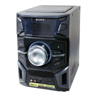
Exploded view showing the main external and internal components.

Front Panel Assembly

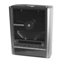
Exploded view detailing the front panel and associated parts.

Top Panel Assembly

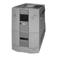
Exploded view of the top panel and its components.

Chassis Assembly

Exploded view of the chassis and associated mounting parts.

Section 7 Electrical Parts List

Power Supply Components

List of electrical parts for the AMP SMPS and Regulator boards.

Other Component Lists

List of electrical parts for Panel, Tuner, and Module sections.

Related product manuals