EasyManua.ls Logo

Sony HCD-EP414 User Manual

Sony HCD-EP414
42 pages
To Next Page IconTo Next Page
Page #1 background imageLoading...
Page #1 background image
HCD-EP414
AEP Model
E Model
Australian Model
SERVICE MANUAL
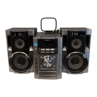
MICRO HI-FI COMPONENT SYSTEM
Sony Corporation
Home Audio Company
Published by Sony Engineering Corporation
9-877-473-01
2003F1678-1
© 2003.06
HCD-EP414 is the Amplifier, CD player, Tape
Deck and Tuner section in CMT-EP414.
SPECIFICATIONS
Ver 1.0 2003. 06
CD player section
System Compact disc and digital
audio system
LaserSemiconductor laser
(
λ=780 nm)
Emission duration:
continuous
Frequency response 2 Hz – 20 kHz (±0.5 dB)
Tape deck section
Recording system 4-track 2-channel stereo
Frequency response 50 – 13,000 Hz (±3 dB),
using Sony TYPE I
cassettes
Tuner section
FM stereo, FM/AM superheterodyne tuner
FM tuner section
Tuning range 87.5 – 108.0 MHz (50-kHz
step)
Antenna FM lead antenna
Antenna terminals 75 ohms balanced
Intermediate frequency 10.7 MHz
AM tuner section
Tuning range
European model: 531 – 1,602 kHz
(with the tuning interval
set at 9 kHz)
Other models: (with the tuning interval
set at 10 kHz)
531 – 1,602 kHz
(with the tuning interval
set at 9 kHz)
Antenna AM loop antenna, external
antenna terminal
Intermediate frequency 450 kHz
Amplifier section
European model:
DIN power output (rated): 11 + 11 W
(6 ohms at 1 kHz, DIN)
Continuous RMS power output (reference):
15 + 15 W
(6 ohms at 1 kHz, 10%
THD)
Music power output (reference):
25 + 25 W
Other models:
The following measured at AC 230 V or AC 120 V, 50/
60 Hz
DIN power output (rated): 11 + 11 W
(6 ohms at 1 kHz, DIN)
Continuous RMS power output (reference):
15 + 15 W
(6 ohms at 1 kHz, 10%
THD)
Inputs
MD IN (phono jacks):
Sensitivity 800 mV,
impedance 47 kilohms
Outputs
PHONES (stereo minijack):
Accepts headphones with
an impedance of 8 ohms or
more
SPEAKER: Accepts impedance of 6 to
16 ohms.
— Continued on next page —
CD
Section
TAPE
Section
Model Name Using Similar Mechanism HCD-EP515
Base Unit Name BU-K7BD44B
Optical Pick-up Name KSM-213EDP
Model Name Using Similar Mechanism HCD-EP515
Tape Transport Mechanism Type CMAL1Z240A
jomi
Question and Answer IconNeed help?

Do you have a question about the Sony HCD-EP414 and is the answer not in the manual?

Sony HCD-EP414 Specifications

General IconGeneral
TypeMini Hi-Fi System
CD PlayerYes
Radio TunerFM/AM
BluetoothNo
CD Player TypeSingle Disc
OutputsHeadphone jack
USB PortYes
Speaker Configuration2.0
FunctionsCD, Radio, USB
Cassette DeckYes
Speakers2 Speakers
InputsAuxiliary Input

Summary

SPECIFICATIONS

Amplifier Section Specifications

European and other models' power output, impedance, and sensitivity.

Speaker and Output Specifications

Speaker impedance and headphone jack requirements.

CD Player Section Specifications

CD player system, laser type, and frequency response.

Tape Deck Section Specifications

Tape deck recording system and frequency response.

Tuner Section Specifications

FM/AM tuning ranges, antenna inputs, and IF frequencies.

SERVICING NOTES

Chip Component Handling

Precautions for replacing chip components and tantalum capacitors.

Flexible Circuit Board Repair

Guidelines for repairing flexible circuit boards, including soldering temperature.

Optical Pick-up & Laser Safety

Notes on handling the optical pick-up block and laser diode safety.

Safety-Related Component Warning

Warning about critical safety components identified by specific marks.

GENERAL INFORMATION

Main Unit Controls

Alphabetical list of main unit functions and button descriptions.

Remote Control Operation

Button descriptions and operational guide for the remote control.

DISASSEMBLY PROCEDURES

Disassembly Sequence Overview

Flowchart showing the order of disassembly for unit components.

Rear Cabinet Disassembly

Steps for removing the rear cabinet.

CD Cabinet & Front Panel Disassembly

Steps for disassembling the CD cabinet and front panel sections.

Base Unit Disassembly

Steps for removing the base unit (BU-K7BD44B).

Control & Back Light Board Disassembly

Steps for removing the control and back light boards.

Tape Mechanism Deck Disassembly

Steps for removing the tape mechanism deck (CMAL1Z240A).

Cassette Door Assembly Disassembly

Steps for disassembling the cassette door assembly.

Power & Main Board Disassembly

Steps for removing the power board and main board.

MECHANICAL ADJUSTMENTS

Adjustment Precautions

General precautions before performing mechanical adjustments.

Torque Measurement Specifications

Required torque values for various mechanical adjustments.

ELECTRICAL ADJUSTMENTS

CD Section Adjustment Checks

General notes and checks for the CD section adjustments.

S-curve Waveform Check

Procedure and expected waveform for S-curve check.

RFAC Signal Level Check

Procedure and expected waveform for RFAC signal level check.

RFDC Signal Level Check

Procedure and expected waveform for RFDC signal level check.

DIAGRAMS AND SCHEMATICS

Circuit Board Locations

Visual guide to the location of main circuit boards within the unit.

Diagram Notes and Symbols

Explanations of common notes, abbreviations, and symbols used in diagrams.

Waveform Examples

Illustrations of waveforms for specific test points in electrical adjustments.

CD Section Block Diagram

Functional block diagram illustrating the CD section's circuitry and signal flow.

Main Section Block Diagram

Functional block diagram illustrating the main unit's circuitry and signal flow.

CD Section Printed Wiring Board

Component layout and PCB traces for the CD section's printed wiring board.

CD Section Schematic Diagram

Detailed circuit schematic for the CD section.

Main Section Printed Wiring Board

Component layout and PCB traces for the main section's printed wiring board.

Main Section Schematic Diagram

Detailed circuit schematic for the main section.

Control Section Printed Wiring Board

Component layout and PCB traces for the control section's printed wiring board.

Control Section Schematic Diagram

Detailed circuit schematic for the control section.

Power Section Printed Wiring Board

Component layout and PCB traces for the power section's printed wiring board.

Power Section Schematic Diagram

Detailed circuit schematic for the power section.

IC Block Diagrams (CD Board)

Internal functional block diagrams for key integrated circuits on the CD board.

IC801 Pin Function Description

Detailed description of each pin's function for IC801 (System Controller).

EXPLODED VIEWS

Cabinet Section Exploded View

Exploded view and parts list for the cabinet section.

Front Panel Section Exploded View

Exploded view and parts list for the front panel section.

CD Cabinet Section Exploded View

Exploded view and parts list for the CD cabinet section.

Base Unit Section Exploded View

Exploded view and parts list for the base unit section.

ELECTRICAL PARTS LIST

Backlight Board Parts

List of electronic components for the backlight board.

CD Board Parts

List of electronic components for the CD board.

Main Board Parts

List of electronic components for the main board.

Control Board Parts

List of electronic components for the control board.

REVISION HISTORY

Version 1.0 Details

Revision history entry for version 1.0, dated 2003.06.

Related product manuals