Do you have a question about the Sony HCD-EX88 and is the answer not in the manual?
Details operational parameters for CD, amplifier, USB, and tuner sections.
Important warnings for component replacement and circuit board repair.
Step-by-step guide for disassembling the unit into major sections.
Block diagrams, schematics, PWB layouts, and electrical parts lists.
Essential notes for handling optical pick-up, laser diode, and unleaded solder.
Information on identifying different model variations based on labels.
Crucial steps for discharging capacitors on the AMP SMPS board.
Guidelines for installing a new optical unit and handling static prevention solder bridges.
A visual guide showing the sequence of disassembling major units like cases, panels, and decks.
Instructions for removing side cases and the top panel using screws and claws.
Instructions for removing the back panel section, involving covers and wires.
Detailed steps for removing the AMP SMPS board, including connections and brackets.
Activates LEDs and display segments; includes version and key test modes.
Procedures for locking the CD tray and entering CD ship mode for maintenance.
Guidelines for focus bias check (CD) and FM auto stop check (Tuner).
Detailed pin functions for the USB controller IC (IC901) on the BD76 board.
Pin functions for the System Control IC (IC302) on the Panel board.
Additional pin functions for the System Control IC (IC302) on the Panel board.
An exploded view of the entire unit, showing major external and internal parts.
Detailed list of capacitors, coils, resistors, semiconductors, and connectors for the EX66 AMP SMPS board.
Continuation of the parts list for EX66 AMP SMPS, including ICs, transistors, and jumpers.
Lists resistors, transformers, terminal boards, thermistors, and varistors for the EX66 AMP SMPS.
Lists capacitors, connectors, diodes, and jumper resistors for the EX66 AMP SMPS.
Lists capacitors, connectors, diodes, and thermistors for the EX88 AMP SMPS.
| Brand | Sony |
|---|---|
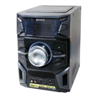
| Model | HCD-EX88 |
| Category | Stereo System |
| Language | English |