SERVICE MANUAL
Sony Corporation
Personal Audio Division
Published by Sony Techno Create Corporation
US Model
Canadian Model
AEP Model
UK Model
E Model
Australian Model
COMPACT DISC DECK RECEIVER
9-879-904-04
2006C16-1
© 2006.03
Ver. 1.3 2006.03
SPECIFICATIONS
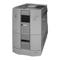
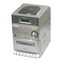
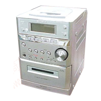
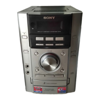
HCD-EC50
HCD-EC50 is the Amplifier, CD player, Tape
Deck and Tuner section in MHC-EC50.
Main unit
AUDIO POWER SPECIFICATIONS
POWER OUTPUT AND TOTAL HARMONIC DISTORTION:
(The United States model only)
With 6 ohm loads, both channels driven, from 120 – 10,000 Hz; rated 50 watts
per channel minimum RMS power, with no more than 10% total harmonic
distortion from 250 milliwatts to rated output.
Amplifier section
Continuous RMS power output (reference): 50 + 50 W (6 ohms at 1 kHz,
10% THD)
North-American model :
DIN poewer output (rated): 24 + 24W (6 ohms at 1 kHz, DIN)
Continuous RMS power output (reference): 30 + 30W (6 ohms at 1 kHz,
10% THD)
Music power output (reference): 60 + 60W
DIN poewer output (rated): 40 + 40W (6 ohms at 1 kHz, DIN)
Continuous RMS power output (reference): 50 + 50W (6 ohms at 1 kHz,
10% THD)
European model :
The following are measured at AC 240V, 50/60 Hz (Australian model) ,
AC 120V, 220 or 240V, 50/60 Hz (other models)
Inputs
AUDIO IN (stereo mini jack): Sensitivity 800 mV, impedance 47 kilohms
Outputs
PHONES (stereo mini jack): Accepts headphones with an impedance of 8
ohms or more
SPEAKER: Accepts impedance of 6 ohms
CD player section
System: Compact disc and digital audio system
Laser Diode Properties
Emission duration: continuous
Laser Output*: Less than 44.6µW
* This output is the value measurement at a distance of 200mm from the
objective lens surface on the Optical Pick-up Block with 7mm aperture.
Frequency response: 20 Hz – 20 kHz
Signal-to-noise ratio: More than 90 dB
Dynamic range: More than 90 dB
Tape deck section
Recording system: 4-track 2-channel, stereo
Tuner section
FM stereo, FM/AM superheterodyne tuner
Antenna:
FM lead antenna
AM loop antenna
FM tuner section:
Tuning range
North American models: 87.5 – 108.0 MHz (100 kHz step)
Other models: 87.5 – 108.0 MHz (50 kHz step)
Intermediate frequency: 10.7 MHz
AM tuner section:
Tuning range
Norhe American models: 530 – 1,710 kHz (with 10 kHz tuning interval)
531 – 1,710 kHz (with 9 kHz tuning interval)
Other models: 530 – 1,710 kHz (with 10 kHz tuning interval)
531 – 1,602 kHz (with 9 kHz tuning interval)
European model: 530 – 1,602 kHz (with 9 kHz tuning interval)
Intermediate frequency: 450 kHz
General
Power requirements
North American model: AC 120V, 60Hz
European model: AC 230V, 50/60Hz
Australian model: AC 230-240V, 50/60Hz
Other models: AC 120V, 220-230V or 240V, 50/60Hz
Adjustable with voltage selector
Power consumption
North American model: 75W
European model: 70W 0.5W (in Power off)
Other models: 95W
Design and specifications are subject to change without notice.
Model Name Using Similar Mechanism NEW
CD
Base Unit Name BU-K6BD83S-WOD
Section
Optical Pick-up Name KSM-213DCP/C2NP
TAPE Model Name Using Similar Mechanism NEW
Section Tape Transport Mechanism Type H21SB-C05
$IMENSIONSWHDEXCLSPEAKERS!PPROX¾¾MM
-ASSEXCLSPEAKERS .ORTH!MERICANAND%UROPEANMODELS!PPROXKG
/THERMODELS!PPROXKG