SERVICE MANUAL
Sony Corporation
Personal Audio Group
Published by Sony Engineering Corporation
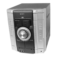
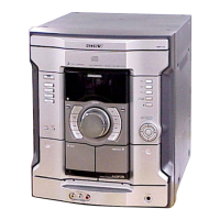
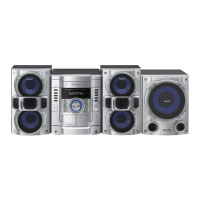
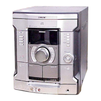
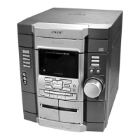
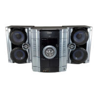
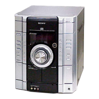
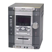
HCD-GX450
US Model
Canadian Model
MINI HI-FI COMPONENT SYSTEM
9-877-534-03
2005H16-1
© 2005.08
• HCD-GX450 is the tuner, deck, CD and
amplifier section in MHC-GX450.
SPECIFICATIONS
Ver. 1.2 2005.08
Amplifier section
AUDIO POWER SPECIFICATIONS
POWER OUTPUT AND TOTAL HARMONIC
DISTORTION:
With 6 ohm loads, both channels driven, from
120 – 10,000 Hz: rated 125 watts per channel
minimum RMS power, with no more than 10%
total harmonic distortion from 250 milliwatts to
rated output.
Front speaker
Continuous RMS power output (reference):
125 + 125 watts (6 ohms at
1 kHz, 10% THD)
Total harmonic distortion less than 0.07% (6 ohms at
1kHz, 60 W)
Sub woofer
Continuous RMS power output (reference):
150 watts (6 ohms at
50 Hz, 10% THD)
Total harmonic distortion less than 0.07% (6 ohms at
50 Hz, 75 W)
CD player section
System Compact disc and digital
audio system
Laser Semiconductor laser
(λ=780 nm)
Emission duration:
continuous
Frequency response 2 Hz – 20 kHz (±0.5 dB)
Wavelength 780 – 790 nm
Signal-to-noise ratio More than 90 dB
Dynamic range More than 90 dB
Tape deck section
Recording system 4-track 2-channel, stereo
Frequency response 50 – 13,000 Hz (±3 dB),
using Sony TYPE I
cassettes
Tuner section
FM stereo, FM/AM superheterodyne tuner
FM tuner section
Tuning range 87.5 – 108.0 MHz
(100-kHz step)
Antenna FM lead antenna
Antenna terminals 75 ohms unbalanced
Intermediate frequency 10.7 MHz
AM tuner section
Tuning range 530 – 1,710 kHz
(with the tuning interval
set at 10 kHz)
531 – 1,710 kHz
(with the tuning interval
set at 9 kHz)
Antenna AM loop antenna
Antenna terminals External antenna terminal
Intermediate frequency 450 kHz
General
Power requirements 120 V AC, 60 Hz
Power consumption
USA models: 265 watts
Canadian models: 330 VA
Dimensions (w/h/d) incl. projecting parts and controls
Amplifier/Tuner/Tape/CD section:
Approx. 280 × 327 ×
425 mm
Mass Approx. 10.0 kg
Design and specifications are subject to change
without notice.
Former Type Models
New Type Models
Model Name Using Similar Mechanism New New
CD
CD Mechanism Type CDM74-F1BD81
CDM74KF-K6BD81C
Section
Optical Pick-up Name
KSM-215DCP/C2NP KSM-213DCP/C2NP
Tape deck Model Name Using Similar Mechanism New New
Section Tape Transport Mechanism Type CWM43FF-05 CWM43FF-05