Do you have a question about the Sony HCD-GX470 and is the answer not in the manual?
Details on amplifier, CD player, tape deck, and tuner sections for GX470/GX570.
Power output and harmonic distortion for GX470 and GX570 front and subwoofer speakers.
System, laser diode properties, frequency response, S/N, and dynamic range.
Recording system, frequency response, and cassette type compatibility.
Essential safety checks after repair, including leakage testing.
FM/AM tuner specifications, tuning range, and intermediate frequency.
Power requirements, consumption, dimensions, and mass of the unit.
Precautions for chip component replacement and flexible circuit board repair.
A visual flowchart detailing the sequence of disassembly steps for the unit.
Steps to remove side cases, top case, CD lid, and front panel.
Steps for removing CD mechanism, mecha deck, main, CD, drive, SW, sensor, and motor boards.
Procedures for removing the optical pick-up block and back panel section.
Precautions for handling the optical pick-up block and checking laser diode emission.
Notes on unleaded solder and releasing the antithest lock function.
Location and identification of model number labels on the unit.
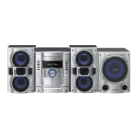
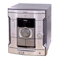
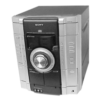
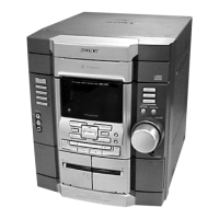
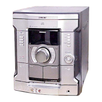
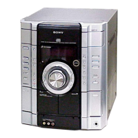
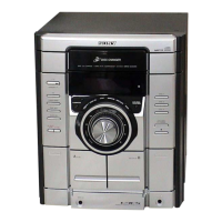
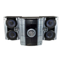
Identification and functions of buttons, jacks, and indicators on the unit and remote.
Initial setup, remote battery insertion, and XM Radio subscription/activation.
Setting the clock, adjusting sound effects, and controlling the subwoofer.
Detailed steps for selecting, playing, pausing, stopping, and managing CD/MP3 disc playback.
Tuning and listening to FM/AM radio and XM satellite radio stations.
Procedures for playing tapes and modifying the unit's display information.
Instructions for connecting headphones and external audio devices.
Important notes regarding MP3 disc compatibility and playback characteristics.
Creating custom CD programs and storing favorite radio stations.
Step-by-step guide for CD Synchro and Manual recording onto tape.
Creating personal sound effects and utilizing Sleep, Play, and Rec timers.
Overall sequence for disassembling the unit into major sections.
Steps to remove side cases, top case, CD lid, and front panel.
Steps for removing CD mechanism, mecha deck, main, CD, drive, SW, sensor, and motor boards.
Procedures for removing the optical pick-up block and back panel section.
Detailed steps and screw locations for removing the left and right side cases.
Detailed steps and claw locations for removing the top case.
Detailed steps for removing the CD lid, including gear and claw locations.
Detailed steps for removing the CD mechanism deck, including flat cables and screws.
Detailed steps for removing the front panel block, including cables and connectors.
Detailed steps for removing the mecha deck, including flat cable and screws.
Detailed steps for removing the back panel section, including cables and connectors.
Detailed steps for removing the main board, including connectors and screws.
Detailed steps for removing the CD board, including screws, cover, and flat cable.
Detailed steps for removing the drive and SW boards, including screws, wire, and connector.
Detailed steps for removing the optical pick-up block, including holder, insulators, and cables.
Detailed steps for removing the sensor board, including tray, belt, and connector.
Detailed steps for removing the table motor (TB) board, including components and screws.
Detailed steps for removing the laser diode (LD) motor board, including components and screws.
Procedures for Cold Reset, Tuning Step Change, Antitheft Lock, and CD Ship Lock.
AMP Test Mode and MC Test Mode for diagnostics and parameter checks.
Modes for checking model/version and displaying CD section error codes.
Explanation of mechanism deck error code format and status indicators.
Explanation of optical pick-up error code format and status indicators.
Modes for enabling limitless CD repeat and managing CD power states.
Precautions, torque measurement, and tape tension measurement for mechanical parts.
Procedures for deck section adjustments, including azimuth alignment.
Detailed procedure for adjusting the record/playback head azimuth for optimal audio quality.
Procedure for checking focus bias using an oscilloscope and eye pattern analysis.
Block diagram illustrating the CD servo control section and its components.
Block diagram of the main section, showing audio and signal paths.
Block diagram of the amplifier section, detailing power and audio stages.
Block diagrams showing panel controls, power supply, and regulators.
Layouts for various boards and notes on schematic/PWB conventions.
Diagram showing the physical location of various circuit boards within the unit.
Detailed printed wiring board layout for the CD board (Component and Conductor sides).
Schematic diagram for the CD board, showing component connections and ICs.
Printed wiring board layouts for the Changer section boards.
Schematic diagrams for the Changer section, detailing connections for motors and sensors.
Printed wiring board layout for the DECK board.
Schematic diagram for the DECK board, showing audio paths and control signals.
Printed wiring board layout for the MAIN board.
Schematic diagram of the MAIN board (part 1/3), showing system controller and related circuits.
Schematic diagram of the MAIN board (part 2/3), detailing ICs and component connections.
Schematic diagram of the MAIN board (part 3/3), showing regulators and various board connections.
Printed wiring board layout for the XM board (GX570 model).
Schematic diagram for the XM board (GX570), detailing the XM receiver and DAC.
Printed wiring board layout for the MIC, AUX, and HP board.
Schematic diagram for the MIC, AUX, and HP board, showing input and output connections.
Printed wiring board layout for the POWER board.
Schematic diagram for the POWER board, detailing power output stages and protection circuits.
Printed wiring board layout for the SUB WOOFER section boards.
Schematic diagram for the SUB WOOFER section, showing amplifier and protection circuits.
Printed wiring board layout for the PANEL board.
Printed wiring board layouts for the KEY LEFT and KEY RIGHT boards.
Schematic diagram for the PANEL section, including remote receiver and key matrix.
Printed wiring board layout for the TRANSFORMER board.
Schematic diagram for the TRANSFORMER board, showing power supply connections.
Oscilloscope waveforms for key signals on CD, DECK, and MAIN boards.
Oscilloscope waveforms for XM and PANEL boards, illustrating signal characteristics.
Block diagrams illustrating internal functions of ICs on CD and Driver boards.
Block diagrams for ICs on the MAIN board, showing audio control and processing features.
Block diagram for XM board IC041, detailing audio data processing.
Comprehensive pinout and function description for the CD DSP IC201.
Pinout and function descriptions for ICs on the MAIN board.
Pinout and function descriptions for ICs on the XM board and other miscellaneous ICs.
Detailed pinout and function description for the System Controller IC901.
Pinout and function descriptions for XM receiver IC001 and other system ICs.
Pinout and function description for the Panel Board IC701, controlling display and tape functions.
Pinout and function description for the XM Receiver IC001 on the XM board.
Exploded view and parts list for the unit's case components.
Exploded view and parts list for the panel board and associated controls.
Detailed exploded view and parts list for panel board components like knobs and keys.
Exploded view and parts list for the top lid section, including display window and screws.
Exploded view and parts list for the front panel assembly, including cassette box and springs.
Exploded view and parts list for the main board and associated components like transformers and fans.
Exploded view and parts list for the power and subwoofer board assemblies.
Exploded view and parts list for chassis components, fuses, and transformers.
Exploded view and parts list for the CD mechanism deck (part 1), showing gears and motors.
Exploded view and parts list for the CD mechanism deck (part 2), including motors, boards, and pick-up block.
Detailed lists of capacitors and resistors used in the unit with part numbers and specifications.
Lists of connectors, ICs, diodes, and jumper resistors with part numbers and types.
Lists of transistors, switches, and vibrator components with part numbers.
List of miscellaneous parts including transformers, fuses, and cables.
Continuation of the list for resistors and capacitors with detailed part numbers and specifications.
Continuation of the list for transistors and resistors with part numbers and specifications.
Continuation of the list for resistors, switches, and diodes with part numbers.
Continuation of the list for capacitors and switches with part numbers and specifications.
Continuation of the list for capacitors, connectors, and diodes with part numbers.
List of ICs and transistors with part numbers and specific model designations.
Continuation of the list for transistors and resistors with part numbers and specifications.
Continuation of the resistor list with part numbers and specifications, including model variations.
Continuation of the resistor list with part numbers and specifications, including model variations.
Continuation of the list for resistors, switches, vibrator, and connectors with part numbers.
Continuation of the list for resistors and capacitors with part numbers and specifications.
Continuation of the list for connectors, ICs, diodes, and jumpers with part numbers.
Continuation of the list for ICs, jumpers, transistors, resistors, relays, thermistors, and connectors.
Continuation of the list for transformers, transistors, resistors, and capacitors with part numbers.
Continuation of the list for resistors and vibrator components with part numbers.
Details changes to the DECK board, including new part numbers and descriptions.
Comparison of former and new part numbers for the DECK board.
Explanations of symbols, marks, and signal paths used in diagrams and PWB layouts.
Printed wiring board layout for the DECK board (Component Side).
Schematic diagram for the DECK board, showing circuit details and connections.
Details changes to MAIN and KEY RIGHT boards, including new part numbers and descriptions.
Comparison of former and new part numbers for MAIN and KEY RIGHT boards.
Explanations of conventions for PWB layouts and schematic diagrams.
Printed wiring board layout for the MAIN board.
Schematic diagram of the MAIN board (part 1/3), showing system controller and related circuits.
Continuation of the MAIN board schematic diagram (part 1/3).
Schematic diagram of the MAIN board (part 2/3), detailing ICs and component connections.
Printed wiring board layout for the KEY RIGHT board.
Schematic diagram for the KEY RIGHT board.
Detailed lists of capacitors and resistors used in the unit with part numbers and specifications.
Continuation of the list for capacitors, connectors, diodes, and jumpers with part numbers.
Continuation of the list for ICs, transistors, and resistors with part numbers.
Continuation of the resistor list with part numbers and specifications, including model variations.
Continuation of the resistor list with part numbers and specifications, including model variations.
Continuation of the list for resistors and vibrator components with part numbers.
Table detailing the revision history of the service manual, including version, date, and description.
| Type | Mini Hi-Fi System |
|---|---|
| PMPO | 1000 W |
| CD Player | Yes |
| Radio Tuner | FM/AM |
| Bluetooth | No |
| USB Playback | Yes |
| Cassette Deck | Yes |
| Speakers | 2 Speakers |