EasyManua.ls Logo

Sony HCD-GX45 Service Manual

Sony HCD-GX45
78 pages
To Next Page IconTo Next Page
Page #1 background imageLoading...
Page #1 background image
1
Ver 1.0 2003. 07
Model Name Using Similar Mechanism NEW
CD CD Mechanism Type CDM74F-K6BD71A
Section Base Unit Name BU-K6BD71A
Optical Pick-up Name KSS-213DCP
Tape Deck Model Name Using Similar Machanism CX-JT8
Section Tape Transport Mechanism Type CWM43FF-13
SERVICE MANUAL
US Model
Canadian Model
HCD-GX45
AEP Model
UK Model
Australian Model
HCD-RG440
HCD-GX45/RG440
AUDIO POWER SPECIFICATIONS
(HCD-GX45 USA model only)
POWER OUTPUT AND TOTAL HARMONIC
DISTORTION:
With 6 ohm loads, both channels driven, from
120 – 10,000 Hz; rated 120 watts per channel
minimum RMS power, with no more than 10 %
total harmonic distortion from 250 milliwatts to
rated output.
Amplifier section
North American models:
HCD-GX45:
Front speaker
Continuous RMS power output (reference):
120 + 120 watts (6 ohms at
1 kHz, 10% THD)
Total harmonic distortion less than 0.07% (6 ohms at
1 kHz, 60 W)
Sub woofer
Continuous RMS power output (reference):
120 watts (6 ohms at
60 Hz, 10% THD)
Total harmonic distortion less than 0.07% (6 ohms at
60 Hz, 60 W)
European and Russian models:
HCD-RG440:
Front speaker
DIN power output (rated): 80 + 80 watts
(6 ohms at 1 kHz, DIN)
Continuous RMS power output (reference):
100 + 100 watts (6 ohms at
1 kHz, 10% THD)
Music power output (reference):
200 + 200 watts (6 ohms at
1 kHz, 10% THD)
SPECIFICATIONS
Sub woofer
DIN power output (rated): 80 watts (6 ohms at
60 Hz, DIN)
Continuous RMS power output (reference):
100 watts (6 ohms at
60 Hz, 10% THD)
Music power output (reference):
200 watts (6 ohms at
60 Hz, 10% THD)
Other models:
HCD-RG440:
The following measured at AC 120, 220, 240 V,
50/60 Hz
DIN power output (rated): 80 + 80 watts
(6 ohms at 1 kHz, DIN)
Continuous RMS power output (reference):
100 + 100 watts (6 ohms at
1 kHz, 10% THD)
Inputs
GAME INPUT AUDIO L/R (phono jacks):
voltage 250 mV,
impedance 47 kilohms
GAME INPUT VIDEO (phono jack):
1 Vp-p, 75 ohms
Outputs
PHONES (stereo mini jack):
accepts headphones of
8 ohms or more
Sony Corporation
Home Audio Company
Published by Sony Engineering Corporation
9-961-068-01
2003G04-1
© 2003. 07
– Continued on next page –
COMPACT DISC DECK RECEIVER
HCD-GX45/RG440 is the
tuner, deck, CD and amplifier
section in MHC-GX45/RG440S.
(Photo: HCD-GX45)

Table of Contents

Question and Answer IconNeed help?

Do you have a question about the Sony HCD-GX45 and is the answer not in the manual?

Sony HCD-GX45 Specifications

General IconGeneral
CD PlayerYes
Radio TunerFM/AM
BluetoothNo
USB PlaybackYes
Cassette DeckYes
TypeMini Hi-Fi System

Summary

Audio Power Specifications

Power Output and Total Harmonic Distortion

Details power output and total harmonic distortion for different loads and frequencies.

Amplifier Section Specifications

Specifies RMS power output and harmonic distortion for North American and European models.

General Specifications

Component and System Specifications

Lists power output, impedance, frequency response, inputs, and outputs for system components.

Speaker and General System Specifications

Speaker System Details

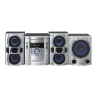
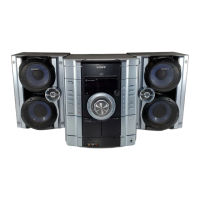
Provides specifications for speaker systems like SS-WG990 and SS-RG440, including units and impedance.

Power Requirements and Consumption

Details power requirements (voltage, frequency) and power consumption for different regions and models.

Supplied Accessories

Cautionary Notes and Safety Procedures

Component Handling and Repair Precautions

Provides guidance on handling chip components, flexible circuit boards, and optical pick-up blocks.

Safety Check-out and Leakage Test

Details the procedure and equipment for testing AC leakage to ensure safe operation.

Special Functions and Checks

CD Disc Tray Lock and Laser Diode Checks

Explains CD tray lock function and procedures for checking laser diode emission and focus search.

Model Identification and Overview

Back Panel Model Identification

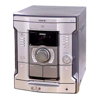
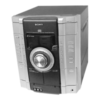
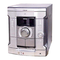
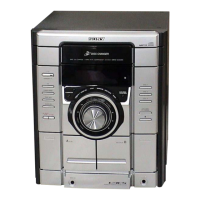
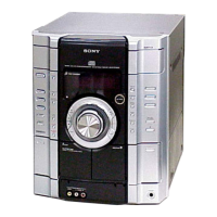
Shows the back panel layout and provides model number information.

Disassembly Procedures Overview

Button Locations and Operation

Main Unit Button Layout

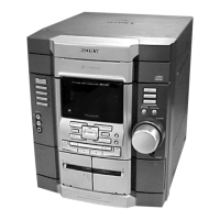
Illustrates button locations on the main unit and references corresponding pages for details.

Remote Control Button Layout

Details button functions and locations on the remote control for various models.

Disassembly Sequence Flowchart

Disassembly: Case and CD Door

Removing the Top Case

Step-by-step instructions and diagrams for removing the top case.

Removing the CD Door

Procedure for removing the CD door, including details on the pulley mechanism.

Disassembly: CD Mechanism Block

Disassembly: Front Panel Section

Disassembly: Tape Mechanism Deck

Procedure for Tape Mechanism Deck Removal

Procedure for removing the tape mechanism deck.

Disassembly: Panel and Associated Boards

Instructions for removing panel boards, LED boards, and remote boards.

Disassembly: Jack Boards and Back Panel

Removing Jack Boards

Procedure for removing the game jack and headphone jack boards.

Removing the Back Panel Section

Steps for removing the back panel section and chassis.

Disassembly: Main Board and Power Boards

Removing the Main Board

Instructions for removing the main board.

Removing Power and Subwoofer Boards

Procedure for removing the power amp and subwoofer boards.

Disassembly: CD Mechanism Related Boards

Removing SW and Driver Boards

Instructions for removing the SW and driver boards.

Removing the CD Block Assembly

Detailed steps for removing the CD block assembly, including insulators and springs.

Disassembly: Sensor and Motor Boards

Removing the Sensor Board

Procedure for removing the sensor board, including tray, belt, and pulley.

Removing the Motor (TB) Board

Instructions for removing the motor (TB) board, including table motor assembly.

Disassembly: Motor (LD) Board and BD Board

Removing the Motor (LD) Board

Procedure for removing the motor (LD) board, including loading motor assembly.

Removing the BD Board

Instructions for removing the BD board.

Disassembly: Optical Pick-up

Test Mode Operations

Cold Reset and Tuner Step Change

Procedures for cold reset, changing tuner step, and setting CD ship mode for customer return.

CD Tray Lock and Amp Test Modes

Explains CD tray lock functionality and the Amp Test Mode for adjustments.

Operational Test Modes

Aging Mode Overview

Performs parallel operation checks of CD and tape sections, repeating until an error or shutoff.

Aging Mode Sequences

Details the aging sequences for the CD and tape deck sections during parallel operation checks.

Specialized Test Modes

GC, MC, Model, and CD Test Modes

Covers GC, MC, Model/Version display, CD error, and CD service modes for testing and maintenance.

Repeat Limit Cancel Function

Enables CD playback to repeat for limitless times, overriding the standard 5-repeat limit.

Electrical Adjustments: CD Section

S-Curve and RF Level Checks

Procedures for checking S-curve symmetry/level and RF signal clarity for CD playback.

IC Pin Descriptions: Main Board (IC309)

IC Pin Descriptions: Main Board (IC310)

IC Pin Descriptions: Panel Board (IC601)

IC Pin Descriptions: Panel Board (Continued)

Block Diagram: CD Section

Block Diagram: Tuner, Tape, and Panel Sections

Block Diagram: Amplifier and Power Supply Section

Block Diagram: Subwoofer Section

Notes on Diagrams and Waveforms

Diagram Notation and Conventions

Explains notation used in printed wiring boards and schematic diagrams, including component markings.

Representative Waveforms

Shows typical waveforms for BD, Main, and Panel boards, crucial for troubleshooting and adjustment.

Printed Wiring Board: CD Mechanism Section (1/2)

Schematic Diagram: CD Mechanism Section (1/2)

Printed Wiring Boards: CD Mechanism Section (2/2)

Schematic Diagram: CD Mechanism Section (2/2)

Schematic Diagram: Main Section (1/4)

Schematic Diagram: Main Section (2/4)

Schematic Diagram: Main Section (3/4)

Schematic Diagram: Main Section (4/4)

Printed Wiring Board: Main Section

Jack Section: Boards and Schematics

Game, Video Out, and H/P Jack Board Layouts

Printed wiring board layouts for game input, video output, and headphone jack connections.

Printed Wiring Boards: Panel Section

Panel and Remote Board Layouts

Layouts of the panel and remote control receiver printed wiring boards.

6 Stream LED Board Layout

Layout of the 6 stream LED board.

Schematic Diagram: Panel Section

Printed Wiring Board: Subwoofer Section

Schematic Diagram: Subwoofer Section

Schematic Diagram: Power Amp Section (1/2)

Schematic Diagram: Power Amp Section (2/2)

Printed Wiring Board: Power Amp Section

Printed Wiring Board: Transformer Section

Schematic Diagram: Transformer Section

IC Block Diagrams: BD Board

IC721 LC78646E-E Block Diagram

Internal block diagram of the LC78646E-E IC, showing its various functional blocks and pins.

IC Block Diagrams: Driver and Main Boards

IC701, 712 BA6956AN (Driver Board)

Block diagram for BA6956AN ICs used on the driver board, detailing motor drivers and control logic.

IC301 M61529FP (Main Board)

Block diagram for the M61529FP IC on the main board, showing audio processing and control functions.

IC Block Diagrams: Main Board (IC201)

Exploded Views: Main Section Assembly

Exploded Views: Front Panel Section (1)

Exploded Views: Front Panel Section (2)

Exploded Views: Front Panel Section (3)

Exploded Views: Main Board Section Assembly

Exploded Views: CD Mechanism Deck (1)

Exploded Views: CD Mechanism Deck (2)

Exploded Views: Base Unit Section

Electrical Parts List: BD Board Components

Capacitors on BD Board

List of capacitors used on the BD board with their part numbers, descriptions, and ratings.

Connectors and Ferrite Beads on BD Board

Lists connectors and ferrite beads on the BD board.

Electrical Parts List: Driver Board Components

ICs and Transistors on Driver Board

Lists integrated circuits and transistors used on the driver board.

Resistors and Switches on Driver Board

Lists resistors and switches used on the driver board.

Electrical Parts List: Panel Board Components

Resistors and Capacitors for Jack Boards

Lists resistors and capacitors for the game jack and H/P jack boards.

Capacitors on Main Board

Details capacitors used on the main board.

Electrical Parts List: Main Board Components (Continued)

Capacitors on Main Board (Continued)

Lists additional capacitors for the main board, often specific to certain regional models.

Electrical Parts List: Main Board Components (Continued)

Connectors, Diodes, ICs, and Jumpers on Main Board

Lists connectors, diodes, ICs, and jumper resistors for the main board.

Coils and Transistors on Main Board

Details coils and transistors used on the main board.

Electrical Parts List: Main Board Components (Continued)

Transistors on Main Board

Lists transistors used on the main board.

Resistors on Main Board

Lists various resistors used on the main board.

Electrical Parts List: Various Boards Components

Resistors for Main and Motor Boards

Lists resistors for the main board and motor boards.

Connectors and Capacitors for Panel Board

Details connectors and capacitors for the panel board.

Electrical Parts List: Panel Board Components (Continued)

Switches, Diodes, and Transistors on Panel Board

Lists switches, diodes, and transistors for the panel section.

Resistors, ICs, Jumpers, and LEDs on Panel Board

Details resistors, ICs, jumpers, and LEDs for the panel section.

Electrical Parts List: Panel Board Components (Continued)

Resistors on Panel Board

Lists various resistors used on the panel board.

Electrical Parts List: Panel Board Components (Continued)

Switches and Vibrator on Panel

Details switches and the vibrator used on the panel.

Capacitors for Power Amp and Sensor

Lists capacitors for power amp and sensor sections.

Electrical Parts List: Power Amp Components

Capacitors and Connectors for Power Amp

Lists capacitors and connectors for the power amp section.

Diodes and Earth Terminals for Power Amp

Details diodes and earth terminals for the power amp section.

Electrical Parts List: Power Amp Components (Continued)

Transistors on Power Amp

Lists transistors used in the power amp section.

Resistors on Power Amp

Lists resistors used in the power amp section.

Electrical Parts List: Power Amp Components (Continued)

Resistors on Power Amp (Continued)

Lists various resistors used in the power amp section.

Electrical Parts List: Power Amp, Remote, Sensor, Subwoofer Components

Capacitors for Power Amp Section

Lists capacitors for the power amp section.

Connectors and Diodes for Remote, Sensor, Subwoofer

Details connectors and diodes for remote, sensor, and subwoofer boards.

Electrical Parts List: Subwoofer Components

Transistors on Subwoofer

Lists transistors used in the subwoofer section.

Resistors on Subwoofer

Lists resistors used in the subwoofer section.

Electrical Parts List: Various Sections Components

Relays, Thermistors, Switches, Diodes, Resistors

Lists relays, thermistors, switches, diodes, and resistors for subwoofer, SW, and transformer sections.

Connectors, Jacks, and Resistors for Video Out/6 Stream LED

Details connectors, jacks, and resistors for video out and 6 stream LED sections.

Miscellaneous Parts List

Revision History

Related product manuals