EasyManua.ls Logo

Sony HCD-H66 User Manual

Sony HCD-H66
71 pages
To Next Page IconTo Next Page
Page #1 background imageLoading...
Page #1 background image
NCD-H66/H70/H77/HT200/H1400
SERVICE
MANUAL
AEP
Model
HCD-H66
HCD-H77
HCD-H66,
HCD-H70,
HCD-H77,
HCD-
HCD-H1200
H1200
and
HCD-H1400
are
the
tuner,
HCD-H1400
deck,
CD
and
amplifier
section
in
FH-
B66CD,
FH-B70CD,
FH-B77CD,
MHC-
UK
Model
1200
and
MHC-1400
respectively.
HCD-H1200
E
Model
Australian
Model
HCD-H70
Dolby
noise
reduction
manufactured
under
license
from
Dolby
Laboratories
Licensing
Corporation.
“DOLBY”
and
the
double-D
symbol
0
are
trademarks
of
tories
Li
ing
C
tion.
Dolby
Laboratories
Licensing
Corporation
PHOTO:
HCD-H70
DIGITAL
AUDIO
COMPACT
SPECIFICATIONS
Model
Name
Using
Similar
Mechanism
|
HCD-H7/H1500
Tuner
Section
ee
CD
Mechanism
Name
CDM13A-5BD3
System
FM
stereo,
FM/AM
Base
Unit
Name
BU-5BD3
er!
rodyne
tuner
FM
tuner
section
laa
a
Model
Name
Using
Similar
Mechanism
|
HCD-H7/H1500
Tuning
range
87.5—108MHz
5
Antenna
Telescopic
antenna
Section
ag
Transpou
BECK
'#
|
TENELTORAL
(HCD-H66/H70/H77)
Mechanism
Type
DECK
B|
TCM-170RB7
cere)
nia
FM
lead
antenna
(HCD-H1200/H1
400)
Antenna
terminals
75
ohms
unbalanced
Peak
music
power
output
Intermediate
frequency
(for
HCD-H70)
280
watts
(6
ohms)
10.7MHz
Inputs
MIX
MIC
(minijack)
AM
tuner
section
:
sensitivity
Tuning
range
For
AEP,
UK,
G
model
lmV,
impedance
MW:
531—1,602kHz
600
ohms
LW:
153—279kHz
For
HCD-H66/H77/
For
IT
model
H1200/H1400
MW:
522—1,611kHz
PHONO
(phono
jacks):
LW:
144—288kHz
sensitivity
5
mV,
For
E,
EA,
AUS
model
impedance
47
kilohms
MW
:
531
~—1,602kHz
For
HCD-H70
SW:
5.95—17.9MHz
VIDEO/AUX
Antenna
AM
loop
antenna,
(phono
jacks):
External
antenna
terminals
sensitivity
450mvV,
Intermediate
frequency
impedance
50
kilohms
450kHz
Outputs
HEADPHONES
(stereo
minijack)
:
Amplifier
Section
accepts
headphones
of
:
8
ohms
or
more.
Continuous
RMS
power
output
SPEAKER:
20+20
watts
accepts
speakers
of
6
to
(6
ohms
at
1kHz,
5%
THD)
16
ohms.
(HCD-H66/H1200)
30+30
watts
(6
ohms
at
1kHz,
5%
THD)
(HCD-H70/H77/H1400)
continued
or
next
page
COMPACT
DISC
DECK
RECEIVER
SONTY.
MICROFILM
Question and Answer IconNeed help?

Do you have a question about the Sony HCD-H66 and is the answer not in the manual?

Sony HCD-H66 Specifications

General IconGeneral
TunerAM/FM
BluetoothNo
USB PortNo
Remote ControlYes
TypeMini Hi-Fi System
CD PlayerYes
Cassette DeckYes
Output Power100W (50W x 2)
Speakers2-way bass reflex speakers

Summary

Specifications Overview

Tuner Section Specifications

Details FM/AM tuner frequency ranges, antenna, and IF.

CD Section Specifications

Details CD mechanism type and similar models.

Amplifier Section Specifications

Details continuous RMS power output for amplifier.

Servicing Notes and General Information

Section 1 Servicing Notes

Important service information and precautions for technicians.

Section 2 General

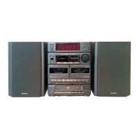
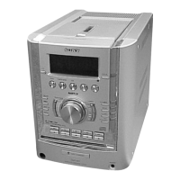
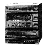
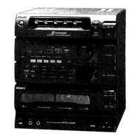
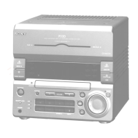
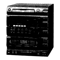
General product information including model identification.

2-1. Parts Identification

Identifies and labels key external and internal parts of the unit.

2-2. Tuner Section Details

Detailed explanation of tuner operations like clock setting and radio tuning.

2-3. Amplifier Section Details

Explanation of audio adjustments, sound quality, and special effects.

2-4. CD Section Details

Explanation of CD playback operations and features.

2-5. Deck Section Details

Explanation of cassette tape playback and recording functions.

Section 3 Disassembly Procedures

Step-by-step instructions for disassembling major unit components.

Section 4 Mechanical Adjustments

Procedures for performing mechanical adjustments on the unit.

Section 5 Electrical Adjustments

Procedures for performing electrical adjustments on the unit.

Section 6 Diagrams

Contains various circuit diagrams, lead layouts, and board locations.

Section 7 Exploded Views

Visual breakdown of parts for assembly and repair.

Section 8 Electrical Parts List

Comprehensive list of all electronic components used in the unit.

Safety Warnings

Critical safety warnings regarding component replacement and handling.

Laser Safety and Handling

Laser Diode Operation Check

Procedure to check the laser diode and focus search operation.

Optical Pick-up Block Handling Notes

Precautions for safe handling of the optical pick-up block unit.

Laser Beam Protection During Servicing

Essential safety instructions to prevent eye exposure to laser radiation.

Laser Diode Properties

Technical specifications and characteristics of the laser diode.

Tuner Operation and Setup

Clock Setting Procedure

Procedure for setting the system's clock time.

Radio Tuning Methods

Instructions for automatic and manual radio station tuning.

Storing and Tuning Preset Stations

Procedure for saving and recalling radio stations.

Antenna Adjustment Guidance

Tips for optimizing antenna placement for better reception.

CD Player Operations

Disc Playing Basics

Instructions for playing CDs, including starting and stopping.

Locating CD Selections

Methods for finding tracks and specific points on a CD.

Shuffle and Program Play Modes

Explanation of random and programmed CD playback modes.

Editing the CD for Recording

Process to edit CD tracks for recording onto tape.

Cassette Deck Operations

Tape Playback Procedures

Instructions for playing cassette tapes and selecting playback modes.

Automatic Fast Winding Playback

Feature allowing playback after fast winding.

Relay Play for Both Decks

Procedure for sequential playback between two cassette decks.

Recording Operation (Deck B)

Steps for recording audio onto a cassette tape.

CD Recording Process

Instructions for recording audio from CDs onto cassette tapes.

Tape Dubbing

Process for copying audio from one tape to another.

Editing the Tape

Methods to edit tape content during dubbing operations.

Timer and Sleep Functions

Timer-Activated Operation

Setting the system to turn on/off automatically for recording or playback.

Sleep Timer Operation

Setting the system to turn off automatically after a preset duration.

Microphone and Mixing Functions

Microphone Mixing Operation

How to connect and use a microphone with audio sources.

Recording Mixed Sound

Process for recording mixed microphone and source audio.

Mechanical and Electrical Adjustments

Mechanical Adjustments Overview

Procedures for mechanical adjustments like cleaning and demagnetizing.

Deck Section Electrical Adjustments

Specific electrical adjustments for the cassette deck section.

Tape Speed and Playback Level Adjustments

Procedures for adjusting tape speed and playback output levels.

Record Bias and Level Adjustments

Procedures for adjusting tape recording bias and input levels.

Tuner Section Adjustments

Calibration procedures for FM and AM tuner sections.

CD Section Adjustments

Calibration procedures for CD player RF and servo systems.

Diagrams and Part Identification

6-1. Semiconductor Lead Layouts

Visual representation of semiconductor pin configurations.

6-2. Circuit Boards Location

Diagrams showing the physical location of circuit boards.

6-4. Schematic Diagram - Tuner/Deck Section

Circuit schematic for the tuner and deck sections.

6-5. Schematic Diagram - Power/Amplifier/Display Section

Circuit schematic for power, amplifier, and display sections.

6-8. Pin Functions

Detailed description of pin functions for key ICs.

[Test Mode] Operation

Explanation of a special service mode for diagnostics and testing.

Exploded Views and Parts Lists

7-1. Case, Power Section Exploded View

Visual breakdown of the unit's case and power supply components.

7-2. Front Panel, Main Board Section Exploded View

Visual breakdown of the front panel and main circuit board assembly.

7-3. MD Chassis Section Exploded View

Visual breakdown of the mechanical chassis assembly.

7-4. Mechanism Deck Section (1) Exploded View

Visual breakdown of the cassette deck mechanism (part 1).

7-5. Mechanism Deck Section (2) Exploded View

Visual breakdown of the cassette deck mechanism (part 2).

7-6. CD Section (1) Exploded View

Visual breakdown of the CD mechanism assembly (part 1).

7-7. CD Section (2) Exploded View

Visual breakdown of the CD mechanism assembly (part 2).

Section 8 Electrical Parts List

Comprehensive list of all electronic components used in the unit.

Related product manuals