Do you have a question about the Sony HCD-HPZ9 and is the answer not in the manual?
Details on CD playback capabilities, including mechanism type and output.
Specifications for the tape deck, including recording system and frequency response.
Details on FM and AM tuner tuning ranges and frequencies.
Specifications for the amplifier, including power output, inputs, and outputs.
Electrical power needs and energy usage details for different models.
Notes on component handling, safety procedures, and leakage testing.
Step-by-step initial disassembly guide for the unit.
Continuation of the step-by-step disassembly process.
Detailed procedure for disassembling the optical pick-up.
Disassembly of side plates, top panel, mechanical deck, and front panel.
Disassembly of main, AMP, rear panel, tuner, power, and CD mechanism boards.
Detailed procedures for disassembling various internal components like arms and gears.
Outline of the assembly sequence for the unit.
Procedures for assembling stocker sections and various gears.
Procedures for assembling levers and sub-gear components.
Verification steps for confirming the correct assembly of the arm section.
Procedures for diagnostic test modes like common and panel tests.
Instructions for ship mode, slot lock mode, and cold reset.
Procedures for CD error codes, servo tests, and power management.
Procedures for torque and tape tension measurements.
Procedure for record/playback head azimuth adjustment.
Identification of various circuit boards within the unit.
Exploded views of side, front, and chassis sections.
Exploded views of CD mechanism components.
Exploded view of the base unit section.
List of electrical parts for the amplifier section.
List of electrical parts for the AU-TC board.
List of electrical parts for BD motor and motor LOD board sections.
List of electrical parts for Panel (1), Panel (2), and Power boards.
| Remote Control | Yes |
|---|---|
| Frequency Response | 20Hz - 20kHz |
| Speaker Impedance | 6 ohms |
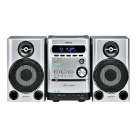
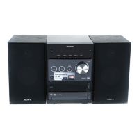
| Type | Mini system |
| Functions | CD Player, Cassette Deck, Radio Tuner |
| Tuner Bands | AM/FM |
| Cassette Deck | Dual |
| Power Output | 100W + 100W |
| Signal-to-Noise Ratio | 80dB |