Do you have a question about the Sony HCD-GP7 and is the answer not in the manual?
Amplifier specifications including DIN power output and impedance.
CD player specifications including laser wavelength and emission duration.
Tape deck specifications for recording system and frequency response.
Tuner specifications including tuning range and intermediate frequency.
General specifications for power consumption, dimensions, and mass.
Precautions for handling chip components during repair.
Precautions for checking laser diode emission.
Precautions for handling the optical pick-up block.
Warning about critical safety components.
Index of buttons and their locations/pages.
Procedure for disassembling top case, main board, and back panel.
Procedure for disassembling front panel and CD mechanism deck.
Procedure for disassembling panel, HP, and VOL boards.
Procedure for disassembling TC board and cassette mechanism.
Procedure for disassembling the CD mechanism.
Procedure for disassembling THR board and DC fan.
Procedure for disassembling speaker and power-amp boards.
Procedure for disassembling sub-power and power boards.
Procedure for disassembling the loading board.
Procedure for disassembling the CD board.
Procedure for disassembling the tray.
Procedure for disassembling optical pick-up and holder.
Clears RAM to initial conditions.
Checks software version, indicator tube, LED, and keyboard.
Activates test mode for various segments.
CD Ship Mode, Disc Tray Lock.
Procedure for tape deck tests.
Mode to select MD or VIDEO function.
Cleaning and handling precautions for mechanical parts.
Table detailing torque specifications for various modes.
Adjustment settings for the deck section.
Procedure for adjusting record/playback head azimuth.
Procedure for adjusting tape recording bias.
Procedure to check the S-curve waveform.
Notes on interpreting schematic and PWB diagrams.
Diagram showing the location of circuit boards.
Block diagram, schematics, and PWB for CD section.
Schematic diagram of the tuner and tape section.
Schematic diagram of the amplifier section.
Schematic and PWB for TC section.
Schematic and PWB for Main section.
Schematic and PWB for Panel section.
Schematic diagram of the power amp section.
Block diagrams for ICs on the CD board.
Exploded view of the entire unit assembly.
Exploded view of the front panel assembly.
Exploded view of the CD mechanism assembly.
Exploded view of the KSM-213D optical pick-up base.
| Number of Channels | 2 |
|---|---|
| CD Player | Yes |
| Remote Control | Yes |
| Frequency Response | 20Hz - 20kHz |
| Total Harmonic Distortion | 0.9% |
| Outputs | Headphones, Speakers |
| Dimensions | 430 x 145 x 350 mm |
| Weight | 9.5 kg |
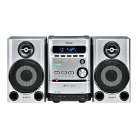
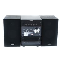
| Type | Mini Hi-Fi System |
| Functions | CD, Radio, Double Cassette |
| Tuner Bands | AM/FM |