Do you have a question about the Sony HCD-SA30 and is the answer not in the manual?
Details amplifier, tuner, and video section parameters.
AC leakage limits and measurement methods for safety.
Precautions for electrostatic breakdown and flexible boards.
Safety instructions for checking laser diode emission.
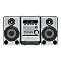
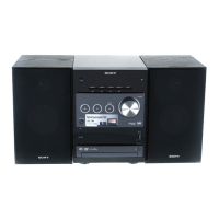
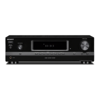
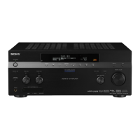
Identification and function of front panel controls and indicators.
Listing of remote control buttons and their corresponding functions.
Procedure for removing the outer case of the unit.
Procedure for removing the DVD mechanism assembly.
Overview of the test mode for diagnosis and adjustment.
List of test discs required for specific operations.
Steps to enter and navigate test mode menus.
Checks board details via serial interface from remote.
Displays ROM version, revision, model type, and region.
Performs sampling and detailed checks of the EEPROM data.
Initializes servo data and adjusts all disc types.
Adjustment procedure for single layer DVD discs.
Adjustment procedure for CD discs.
Adjustment procedure for dual layer DVD discs.
Lists options for manual servo control and adjustments.
Automatically judges and displays the inserted disc type.
Manual setting for DVD disc types.
Manual setting for CD disc types.
Manual setting for hybrid disc types.
Controls servo functions like laser, focus, tracking, and sled.
Performs track jump and layer jump operations for DVDs.
Manually adjusts servo parameters stored in EEPROM.
Automatically adjusts servo parameters stored in EEPROM.
Displays current servo adjusted data stored in EEPROM.
Measures mirror time of chucked discs and writes to EEPROM.
Measures and displays error rates (PI, PO).
Executes aging of the mechanism deck for open/close operations.
Accesses emergency history and clears log data.
Displays and explains the error history of the mechanism deck.
Displays ROM versions for system controllers and front end.
Procedure for adjusting video levels using color bars.
Illustrates the physical location of main circuit boards within the unit.
Block diagram illustrating the RF and servo signal paths and components.
Block diagram illustrating the video signal paths and processing.
Block diagram detailing audio amplifier signal paths.
Block diagram detailing power drivers, headphone amp, and control signals.
| Brand | Sony |
|---|---|
| Model | HCD-SA30 |
| Category | Stereo Receiver |
| Language | English |